12-Head Polishing Machine: Installation Manual

| |
|||
| Document | mdi_p1p51fc20-008 | ||
|---|---|---|---|
| Description | Installation manual for application P1P51FC20-008 | ||
| Drawn up | Davide Mocellin | ||
| Approved | Gabriele Bazzi | ||
| Link: | http://www.qem.eu/doku/doku.php/en/applicazioni/marmo/levigatrice_di_lastre/standard_12_heads/mdi_standard_12_heads/mdi_p1p51fc20-008 | ||
| Language: | English | ||
| Document Release | Description | Notes | Date |
| 02 | New setup configuration | 09/03/2015 | |
All rights reserved on this manual. No part of this document can be copied or reproduced in any form without prior written authorisation. QEM does not insure or guarantee its contents and explicitly declines all liability related to the guarantee of its suitability for any purpose. The information in this document can be changed without notice. QEM shall not be held liable for any error or omission in this document. QEM® is a registered trademark.Microsoft® and MS-DOS® are registered trademarks and Windows® is a trademark of Microsoft Corporation.
1. Setup
 |   password 462 |  |
 | Time (hours, minutes and seconds) |
 | Date (years, months and days) |
 | Password requested |
 | No password requested |
1.1 General Setup


| Parameter | Unit measure | Default | Range | Description |
|---|---|---|---|---|
| PG01 : FIRST LANGUAGE | - | ENG | - | 1 = ENGLISH 2 = ITALIAN 3 = FRENCH 7 = TURKISH 8 = CHINESE 9 = EGYPTIAN 11 = RUSSIAN |
| PG02 : SECOND LANGUAGE | - | ITA | - | |
| PG03 : NUMBER OF HEADS | - | 12 | 1–12 | Number of heads |
| PG04 : NUMBER OF SENSORS | - | 64 | 8 – 64 | Number of sensors on the Scan Bar |
| PG05 : DECIMAL POINT | - | 1 | 0 – 2 | Number of decimals shown for distance measures |
| PG06 : LINEAR STEP | mm | 50.0 | 1.0 – 9999.9 | Linear read spacing. Distance between readings on the Scan bar state |
| PG07 : CROSS STEP | mm | 50.0 | 1.0 – 9999.9 | Cross read spacing. Distance between the sensors on the Scan bar |
| PG08 : SLABS FEED FROM | - | 0 | 0 – 1 | Which side the display is installed 0 = LEFT 1 = RIGHT |
| PG09 : ABRASIVE ANALOG | - | 0 | 0 – 1 | Enable analog IN for abrasive control |
| PG10 : CURRENT MANAGEMENT | - | 0 | 0 – 1 – 2 | 1 = read only no control 2 = read and control |
| PG11 : N°WARNING = ALARM | - | 10 | 0 – 99999 | Number of warning events to generate an alarm |
| PG12 : MOTORS OUTPUT | - | 0 | 0 – 1 | Head operating mode 0 = CONSTANT, always active when heads are operating 1 = PULSE, active for a set time (PG13). |
| PG13 : PULSE TIME | s | 0.000 | 0 – 99.999 | Heads active time, if operation set to PULSE |
| PG14 : MOT.SEQ.TIME ON | s | 1.000 | 0 – 99.999 | Delay between the startup of one motor and another (startup sequence) |
| PG15 : MOT.SEQ.TIME OFF | s | 0.200 | 0 – 99.999 | Delay between the shutoff of one motor and another (stop sequence) |
| PG16 : MOT.OFF SLAB OUT | s | 0.000 | 0 – 99.999 | Delay before the motor shutoff sequence, when no slabs are on the belt |
| PG17 : PRE-START TIME | s | 3.0 | 0 – 9999.9 | Delay after Start for machine to start working (there is a warning during this time). If less than the motor startup time, the greater is counted. |
| PG18 : LUBRIC. TIME ON | s | 0.0 | 0 – 9999.9 | Lubrication time. |
| PG19 : LUBRIC. TIME OFF | min | 0.0 | 0 – 9999.9 | Lubrication off time. |
| PG20 : BRUSH EARLY | mm | 0.0 | 0 – 9999.9 | Brush down anticipation |
| PG21 : BRUSH DELAY | mm | 0.0 | 0 – 9999.9 | Brush up delay |
| PG22 : SPRAY EARLY | mm | 0.0 | 0 – 9999.9 | Spray on anticipation |
| PG23 : SPRAY DELAY | mm | 0.0 | 0 – 9999.9 | Spray off delay |
1.2 Beam Setup


| Parameter | Unit measure | Default | Range | Description |
|---|---|---|---|---|
| PB01 : MEASURE | mm | 0.1 | 0 – 99999.9 | Distance in unit measures, made by the Beam for the encoder pulses at the parameter pulse. |
| PB02 : PULSE | - | 1 | 0 – 999999 | Beam encoder pulses, multiplied by 4 to get the distance at the parameter measure. The measure to pulse ratio, is the encoder resolution and must be between 1 and 0.000935. |
| PB03 : TOLERANCE | mm | 0.50 | 0 – 99999.99 | Maximum deviation of the count around the positioning, for it to be considered correct |
| PB04 : ENABLE TIME | s | 0.200 | 0.000 – 9.999 | Time before starting the Beam movement |
| PB05 : DISABLE TIME | s | 0.200 | 0.000 – 9.999 | Time after ending the Beam movement |
| PB06 : MAXPOS | mm | 99999.9 | -99999.9 – 99999.9 | Maximum Beam position |
| PB07 : MINPOS | mm | -99999.9 | -99999.9 – 99999.9 | Minimum Beam position |
| PB08 : ACCELERATION MODE | - | 0 | 0 – 1 | Type of acceleration 0 = referred to max speed 1 = constant at all speeds |
| PB09 : ACCELERATION TIME | s | 1.00 | 0.00 – 9.99 | Time from 0 to maximum speed |
| PB10 : DECELERATION TIME | s | 1.00 | 0.00 – 9.99 | Time from maximum to 0 speed |
| PB11 : INVERSION TIME | s | 0.50 | 0.00 – 9.99 | Anti-stress protection against rapid direction changes |
| PB12 : DISACTIVATION TIME | s | 0 | 0 – 99999 | Maximum delay for the Beam, before the axis enable output is disactivated |
| PB13 : BRAKE OUTPUT | - | 1 | 0 – 1 | Enable mode for the axis output 0: Output ON before axis movement and OFF at end, see PB04 & PB05 1: Output ON before axis movement and OFF only in emergency |
| PB14 : HOMING POSITION | mm | 0.0 | -99999.9 – 99999.9 | Axis Homing position |
| PB15 : HOMING SPEED | % | 5 | 1 – 100 | Axis speed, when searching for the homing sensor |
| PB16 : HOMING SLOW SPEED | % | 2 | 1 – 100 | Speed for disengaging the homing sensor. |
| PB17 : HOMING DIRECTION | - | 0 | 0 – 1 | Axis direction for Homing 0 = FORWARD 1 = BACKWARD |
| PB18 : STOP POSITION | - | 0 | 0 – 1 | Beam position, when the cycle is stopped 0 = PB06, maximum position, 1 = PB07, minimum position |
| PB19 : CHANGE ABR POSITION | mm | 0.0 | -99999.9 – 99999.9 | Beam position when changing abrasive |
| PB20 : MAX SPEED | mm/min | 1000 | 0 – 9999999 | Beam speed at an analog output of 10V |
| PB21 : FEEDFORWARD | % | 100.0 | 0.0 – 200.0 | Percentage speed multiplier to generate the feed-forward quota of the analog output |
| PB22 : PROPORTIONAL GAIN | - | 0.010 | 0.000 – 9.999 | The follow error multiplier to generate the proportional quota of the analog output |
| PB23 : INTEGRAL TIME | s | 0.000 | 0.000 – 9.999 | The integration time coefficient of the follow error. The error integration multiplier to generates the integral quota of the analog output |
| PB24 : DERIVATIVE TIME | s | 0.000 | 0.000 – 9.999 | The derivative time coefficient of the follow error. The error derivation multiplier to generates the derivative quota of the analog output |
| PB25 : MAX FOLLOW ERROR | mm | 0.00 | 0.00 – 99999.99 | The maximum drift between the calculated axis position and real axis position |
| PB26 : OFFSET | bit | 0 | -32768 – 32767 | Bit value added to the analog output to compensate any supply voltage irregularities |
1.3 Belt Setup


| Parameter | Unit measure | Default | Range | Description |
|---|---|---|---|---|
| PBT01 : MEASURE | mm | 0.1 | 0 – 99999.9 | The space, in the unit measure, travelled by the Beam to obtain the encoder pulses, set at the parameter pulse. |
| PBT02 : PULSE | - | 1 | 0 – 999999 | The pulses supplied by the Beam encoder, multiplied by 4 to obtain the space, set at the parameter measure. The measure to pulse ratio, is the encoder resolution and must be between 1 and 0.000935. |
| PBT03 : BELT SPEED BY | - | 0 | 0 | Only display mode (0) |
| PBT04 : MAX SET SPEED | m/min | 0.0 | 0 – 999.9 | Max speed limit |
| PBT05 : MIN SET SPEED | m/min | 0.0 | 0 – 999.9 | Min speed limit |
| PBT06 : BELT OUTPUT | - | 0 | 0 – 1 | Belt operating mode 0 = CONSTANT, always active when belt is operating 1 = PULSE, active for a set time (PBT07) |
| PBT07 : PULSE TIME | s | 0.0 | 0 – 9.999 | Belt active time, if operation set to PULSE |
| PBT08 : BELT DELAY | s | 0.0 | 0 – 9.999 | Belt start delay after all heads ON |
| PBT09 : 10V SPEED | m/min | 5.0 | 0 – 999.9 | Speed at 10V analog output |
| PBT10 : OFFSET | bit | 0 | -32768 – 32767 | Bit value added to the analog output to compensate any supply voltage irregularities |
1.4 Heads Setup


| Parameter | Unit measure | Default | Range | Description |
|---|---|---|---|---|
| PH01 : MAXIMUM WORK DIAMETER | mm | 400.0 | 0 – 99999.9 | Maximum work diameter |
| PH02 : MINIMUM WORK DIAMETER | mm | 330.0 | 0 – 99999.9 | Mininum work diameter |
| PH03 / PH14 : TIME TO STANDY UP | s | 0.500 | 0 – 999.999 | The up movement time for the standby up |
| PH15 : UP DELAY | s | 0.000 | 0 – 999.999 | Delay time for the total up of the heads |
| PH16 : READ DELAY | s | 1.000 | 0 – 999.999 | Delay from head down and reading |
| PH17 : READ AGAIN | s | 5.000 | 0 – 999.999 | Repeat read time with head down |
1.5 Head Spacing Setup


Set the distance from the Scan bar to the Center of each Head, Spray and Brush
1.6 Sensors Setup


| Sensor enabled | Sensor disabled |
N.B. Two adjacent sensors cannot be disabled. Only disable alternate sensors.
| Parameter | Unit measure | Default | Range | Description |
|---|---|---|---|---|
| PS01 : SENSOR TYPE | - | 0 | 0 – 1 | Scan bar input logic 0 = N.O., Normally Open 1 = N.C., Normally Closed |
2. Calibration
2.1 Beam and Belt


2.1.1 Resolution


Procedure

-
 and check ENCODER increases (Analog out +1 Volt)
 -
 and check ENCODER decreases (Analog out -1 Volt)
 -
A - A' = Maximum MEASURE
-
Note the start position (A)
-
 Zero-set ENCODER
 -
Move the axis from A to A'
-
Note the ENCODER reading and enter it in PULSE
-
Measure the distance from A to A' = space delta
-
Enter the A - A' space delta in MEASURE
Important:
-
PULSE must always be greater than MEASURE (recommended MEASURE x 10 = PULSE)
-
Enter MEASURE in the set unit measure format. e.g. unit measure = 0.1 mm and space delta = 133.5mm, enter 1335 in MEASURE
2.1.2 Calibration


Settings in yellow can be modified for the calibration.
Service data is in green and only used for the setup procedure.
| Parameter | Unit measure | Default | Range | Description |
|---|---|---|---|---|
| VOLTAGE OUTPUT | V | 0.0 | -10.0 – 10.0 | Output voltage, with 0.1V precision, sent directly to the device |
| OFFSET | bit | 0 | -32768 – 32767 | Bit offset (and voltage conversion) added to the analog output to compensate any supply voltage irregularities |
| SPEED | mm/min | - | - | The real axis speed |
| MAX SPEED | mm/' | 1000 | 0 – 9999999 | Axis speed at an analog output of 10V |
| POSITION | mm | - | - | The real axis position |
First complete the following procedures:
-
RESOLUTION: set the resolution.
-
MAX POSITION: enter a very large positive setting (e.g. 99999.9 mm)
-
MIN POSITION: enter a very large negative setting (e.g. - 99999.9 mm)
IMPORTANT! Essential conditions for the all procedures:
 The emergency button must shut off the power to the motors so that the machine is in a safety condition.
 All emergency conditions on the machine must be eliminated.
Procedures
| Offset | |
|---|---|
| 1 |  to start calibration to start calibration |
| 2 | Set VOLTAGE OUTPUT = 0 |
| 3 | Regulate the OFFSET (directly by |
| 4 |  to quit calibration to quit calibration |
| Rotation direction and count | |
|---|---|
| An output voltage > 0 increases POSITION | |
| 1 | to start calibration |
| 2 | Enter VOLTAGE OUTPUT = 1.0 |
| 3 | Check that POSITION increases |
| 4 | to exit calibration and check that VOLTAGE OUTPUT goes to 0 immediately |
| 5 | If the motor does not rotate in the correct direction, change the drive setup or cabling |
| Maximum speed | |
|---|---|
| Setting the maximum axis speed (10V output) | |
| 1 | to enter calibration |
| 2 | Enter VOLTAGE OUTPUT > 1.0 (as close to 10V as possible) |
| 3 | Note the SPEED reading |
| 4 | Calculate the MAX SPEED: MAX SPEED = (10 x SPEED) / VOLTAGE OUTPUT |
| 5 | to exit calibration and check that VOLTAGE OUTPUT goes to 0 immediately |
| 6 | Enter the above calculation result in MAX SPEED |
2.1.3 P.I.D.


The PI + FF calibration procedure:
Space feedback corrects the axis position according to the follow error reading.
Settings in yellow can be modified for the calibration.
Service data is in green and only used for the setup procedure.
| Parameter | Unit measure | Default | Range | Description |
|---|---|---|---|---|
| VOLTAGE OUTPUT | V | 0.0 | -10.0 – 10.0 | Output voltage, with 0.1V precision, sent directly to the device |
| SPEED | mm/min | - | - | The real axis speed |
| MAX SPEED | mm/' | 1000 | 0 – 9999999 | Axis speed at an analog output of 10V |
| POSITION | mm | - | - | The real axis position |
| DELTA | mm | 0.0 | - | Delta space between two positions |
| SET SPEED | mm/' | 0 | - | Axis speed during positioning |
| ACC. TIME | s | 1.00 | - | Acceleration time during positioning |
| DEC. TIME | s | 1.00 | - | Deceleration time during positioning |
| FEEDFORWARD | % | 100.0 | 0.0 – 200.0 | Percentage speed multiplier to generate the feed-forward quota of the analog output |
| PROP. GAIN | - | 0.010 | 0.000 – 9.999 | The follow error multiplier to generate the proportional quota of the analog output |
| INTEGRAL TIME | s | 0.000 | 0.000 – 9.999 | The integration time coefficient of the follow error. The error integration multiplier to generates the integral quota of the analog output |
| MAX FOLL. ERROR | mm | 99999.9 | 0.0 – 99999.9 | The maximum drift between the calculated axis position and real axis position |
| FOLLOW ERROR | mm | - | - | The real follow error reading |
First complete the following procedures:
-
RESOLUTION: set the resolution.
-
MAX POSITION: enter a very large positive setting (e.g. 99999.9 mm)
-
MIN POSITION: enter a very large negative setting (e.g. - 99999.9 mm)
IMPORTANT! Essential conditions for the all procedures:
Ensure that the emergency button shuts off the power to the motors so that the machine can be put in a safety condition.
All emergency conditions on the machine must be eliminated.
Procedure
| Space Feedback | ||||||||||||||
|---|---|---|---|---|---|---|---|---|---|---|---|---|---|---|
| Important: first complete all previous procedures | ||||||||||||||
| 1 | Enter FEEDFORWARD = 100.0 | |||||||||||||
| 2 | Enter PROP. GAIN = minimum setting (0.001) | |||||||||||||
| 3 | If FOLLOW ERR is not 0, now this reading will reduce with an axis movement | |||||||||||||
| 4 | Enter DELTA = any distance and SET SPEED = a speed (nearly MAX SPEED) | |||||||||||||
| 5 |  to start the axis movements to start the axis movements |
|||||||||||||
| 6 | The axis moves forward by the distance in DELTA at the speed in SET SPEED | |||||||||||||
| 7 | The axis then returns to the start position and repeats the movement | |||||||||||||
| 8 | During the movements note the FOLLOW ERR reading and vary FEEDFORWARD and PROP. GAIN to keep it as low as possible. Setting rules
|
|||||||||||||
| 9 | When the axis movement overshoots MAX FOLLOW ERROR you will see the warning symbol |
|||||||||||||
| 10 |  to quit the procedure to quit the procedure |
|||||||||||||
3. Defaults
 |  |
 |
|
 |
 | Load default settings |
 | Quit without loading |
4. Restore
 password 123456
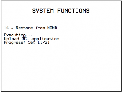
Restore all files.
5. Touchscreen


5.1 Diagnostic


5.1.1 Digital Inputs


See Electric Connection Manual (Wiring connections) for Input Identification
5.1.2 Digital Ouputs


5.1.3 System Info


 | Belt, beam and last piece positions |
 | J1P51 CPU data:
|
 | Enter a Head Number. See virtual Slab position under the specific head. Below see the slab under the Scan bar. |
 | CANBUS network communication state:
|
5.1.4 Encoder count inputs


5.1.5 Analog Inputs/Ouputs


5.1.6 Alarms


 Cancel alarms and restore machine operation
If alarm repeats, a new message is given - If there is no alarm, the Main screen is opened.
| Id | Message | Cause | Remedy |
|---|---|---|---|
| 1 | Air pressure | No air pressure or pressure switch fault (I17 off) | Check pressure switch and cabling |
| 2 | Thermal overload | A cutout has tripped (I161) | Check the cutouts and cables |
| 3 | Beam Inverter fault | Beam inverter fault (I13 off) | Check the inverter and cables |
| 5 | Belt Inverter fault | Belt inverter fault (I15 off) | Check the inverter and cables |
| 6 | Emergency pressed | Emergency button pressed (I01 off) | Release the emergency button and check the cables |
| 7 | No Abrasive | Abrasive worn out and needs changing | Check head abrasive levels |
| 8 | CANBUS comunication error (node 1) | CANopen comm error at node 1 = RMC2M cabinet | Switch the system Off - On. Check the cables |
| 9 | CANBUS comunication error (node 2) | CANopen comm error at node 2 = RMC2M beam | Switch the system Off - On. Check the cables |
| 11 | One head distance over maximum length | A Head distance is too long for the linear step Only during automatic | Check the head distances Increase the linear step (general setup) |
| 12 | Belt encoder fault | No Belt encoder pulses received | Check the encoder, the axis movement, the cables |
| 13 | Beam encoder fault | No Beam encoder pulses received, Follow error | Check the encoder, the axis movement, the cables |
| 15 | Water pressure | No water pressure or pressure switch fault (I18 off) | Check the pressure switch and cables |
| 16 | Beam offset out of range | Beam offset setting is out of limit range | Correct the setting |
| 17 | Roller Inverter fault | Feed roller inverter fault (I16 off) | Check the inverter and cables |
| 18 | Enclosure open | An enclosure is open (I12 off) | Close the enclosure before any work |
| 19 | Pressure regulation error | Motor current out of range | Modify work pressure parameters |
5.1.6.1 Alarm History


Cancel alarms history