~~BOZZA~~
AN005 - How to use stepper motors
0.1 INTRODUCTION
This document describe how to use the H2C40 card for control of stepper motors with Qview software (device settings) and in terms of hardware (card features).
0.2 STEP/DIRECTION COMMAND
The following picture shows the block diagram of a conventional positioning system, or analog output:
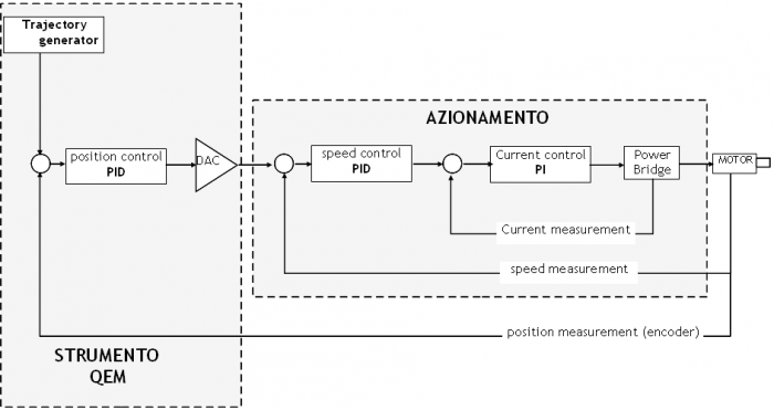
QEM instrument implements the trajectory and loop position generator.
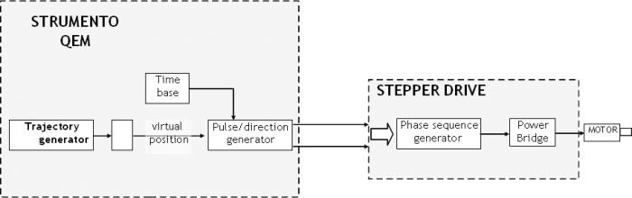
The generator of the trajectory (EANPOS or CAMMING or JOINT device of QMOVE and microQMOVE family) generate the position at each execution (sampling). This value is the position it should take the axis (èalso called “virtual profile”) at each sampling instant. Now, in the drive for stepper motors they represent the impulses that must be provided to move the motor of the steps that match the position. Because each pulse the motor performs a step (or half step or microstep depending on the drive or of its programming) the pulse rate determines the rate of motor displacement.
0.3 PROGRAMMING
The movement of stepper motors can be performed using all systems that are equipped with positioning device having as a output analog voltage (EANPOS, CAMMING3, JOINT) and there is a H2C40 card that implements the pitch/yaw output generation.
The device will be used as positioning for cases with the analog output done d the following notes:
- In the device declaration, on the configuration file, you must set the bidirectional counter input to X.X so that the posit parameter is the value of the virtual position.
- In the device declaration, on the configuration file, you must set the hardware address of the DAC componentof the analog output with the slot number and the keyword PULSE01 or PULSE02 (instead of an01, an02).
- Positioning devices that drive stepper motors work in open loop so you don't need to run the LOOPON command (even if you execute, has no effect on the output of control).
- The pulse parameter must be set to the number of steps per revolution of the motor If you are using a full step resolution. In the case of higher resolutions (created by microstepping drives) the pulse parameter must be set to the number of step/Rev of the motor multiplied for the resolution. For example, having a motor from 200 steps/Rev and a drive set at a resolution of 1/10 by step we will have to set the pulse parameter with value 2000.
- The measure parameter must be set to the value of units of measurement corresponding to one revolution of the motor.
- The maxvel parameter, unlike positioners with analog output where the setting value corresponds to the speed reached by the axis, expressed in units of measurement, when the analogue output is 10V, in the positioner with stepper motors this parameter defines the maximum speed to which you want to move the axis. This speed must be chosen according to the characteristics of the motor and the load, because the torque delivered by a stepper motor is highly dependent on the speed.
0.4 LIMITATIONS
0.4.1 Setting the maxvel parameter
The maxvel value it is also restrictive to the choice of the steering drive resolution (microsteps) since it determines the maximum frequency of pulse signal output. For example, having an application that has the following characteristics:
stepper motor 200 step/Rev
driver with resolution 1/20 od step
screw with step 2mm
max speed motor 2mt/min
The maximum speed corresponds to 1000 rpm so the output frequency must be (1000rpm*4000 pulse/Rev)/60 = 66666 Hz
You must then make sure that the driver Board is able to generate this frequency. Otherwise you have to lower the resolution or reduce the maximum speed; for example the H2C40 card can reach only 50KHz; we will have a maximum possible speed of 750 rpm or by lowering the resolution to 1/10 of step we can get up to 1500rpm.
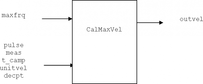
To facilitate the calculation of the maxvel parameter starting from the maximum desired STEP output frequency, you can use the “CalMaxVel” subroutine of the example application “DEMO_L2CZ2”. N.B. This function can be use only with the unitvel = 1 parameter.
0.4.2 Speed
For the special firmware on the pulse generator and the discretization of the exit, the movement speed of the axis is conditioned by the sample time. For what you could see on a system with screw-nut (not necessarily be exactly the same thing on a system with motion transmission with elastic strap) the corresponding rate setting to output frequencies pulse signal not multiple of the sample rate can generate vibrations on the axis. We will get into this condition, for example, if we had a device with sample time of 2msand we wanted to place at a speed to which corresponds a frequency of 10200Hz. The system can generate only multiple frequencies of sampling rate that are 500Hz, so we should set a rate at which corresponds a frequency of 10000Hz or of 10500Hz. What happens when we position precisely to 10200Hz? We will have that for 4 samples will speed 10000Hz and a for a sampling will be 10500Hz, the average speed will be 10200Hz but it's like we had a “noise” superimposed on the frequency of 10000Hz that might make “vibrate” axis. Where possible, therefore, we recommend changing the speed that they respect the rule mentioned above.
In order to facilitate the calculation of the speed does not have the effect of superimposed noise, you can use the “CalVel” subroutine of the sample application “DEMO_L2CZ2”. This subroutine calculates a value approximate speed down compared with a desired value.
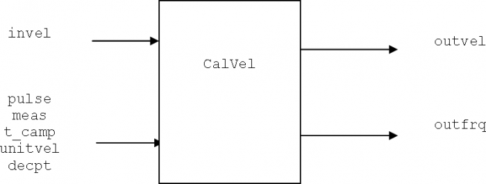
N.B the subroutine functions only with unitvel = 1 (Um/s)
N.B in case of failure the function calculation outvel = -1. There are two possible errors: 1)unitvel = 0 2) you used a sample time which does not allow to generate a finite value for example: 3, 6, 7, 9msec, etc
0.5 HARDWARE CARD
The L2CZ2 card (release hardware 1) allows to command nr. 2 drivers for step motor. The maximun frequency of the STEP output is 50KHz. The outputs are of NPN type with maximum current of 200mA.
The Terminal Board connections are:
| Name | Description |
| COM | Common of STEP1, DIR1, STEP2, DIR2 outputs. Connected to zero volts driving inputs. |
| STEP1 | STEP-DIRECTION outputs for driver 1 (X.PULSE01) |
| DIR1 | |
| STEP2 | STEP-DIRECTION outputs for driver 2 (X.PULSE02) |
| DIR2 |
0.6 APPLICATION EXAMPLE
Here is an example declaring a EANPOS device and moves the position between zero and 100.
0.6.1 Config
;---------------------------------------------
; Project           : TEST_H2C40
; Module Name       : CONFIG
; Author            :
; Date              : 26/04/2007
; Time              : 16.16.56
; Description       :
;---------------------------------------------


;---------------------------------------------
;  Constants Definition
;
;  ConstName  Value
;---------------------------------------------
CONST
TC_EANPOS		0005


;---------------------------------------------
;  GLOBAL Variables Definition
;
;  VarName    Type (F, B, W, L, S)
;---------------------------------------------
GLOBAL
myvel 		L

; - Used in CalVel & CalMaxVel
invel		L
outvel		L
pulse		L
meas		L
tsample		W
unitvel		B
decpt		B
outfrq		L
frqc		S
frqp		L
maxfrq		L

;---------------------------------------------
;  TIMER Variables Definition
;
;  TimerName
;---------------------------------------------
TIMER
timer01


;---------------------------------------------
;  Bus Configuration
;
;  SlotNumber  CardName  Version
;  If not present write '.' in CardName and Version
;---------------------------------------------
BUS
1	992BF	20
2	.		.
3	L2CZ2	.


;---------------------------------------------
;  INTDEVICE Declaration
;---------------------------------------------
INTDEVICE
ep01	EANPOS		TC_EANPOS 	X.X		X.X		X	3.PULSE01
0.6.2 Module 1
;---------------------------------------------
; Project           : TEST_H2C40
; Module Name       : MODULE1
; Author            :
; Date              : 26/04/2007
; Time              : 16.16.59
; Description       :
;---------------------------------------------

	ep01:pulse = 4000
	ep01:measure = 100
	ep01:taccdec = 100
	ep01:minpos = -999999
	ep01:maxpos = 999999
	ep01:setpos = 200
	ep01:unitvel = 1

;- Calculate maxvel for 50KHz step output
	maxfrq = 50000
	pulse = ep01:pulse
	meas = ep01:measure
	tsample = TC_EANPOS
	unitvel = ep01:unitvel
	decpt = ep01:decpt
	CALL CalMaxVel
	IF (NOT(outvel EQ -1)) ; check if an error occur
		ep01:maxvel = outvel
	ENDIF

	INIT ep01
	WAIT ep01:st_init

	myvel = ep01:maxvel/10

MAIN:

; Calculate setvel based on myvel value
	invel = myvel
	pulse = ep01:pulse
	meas = ep01:measure
	tsample = TC_EANPOS
	unitvel = ep01:unitvel
	decpt = ep01:decpt
	CALL CalVel
	IF (NOT(outvel EQ -1)) ; check if an error occur
		ep01:setvel = outvel
	ENDIF

    timer01 = 1000
    WAIT timer01
    ep01:setpos = 100
    START ep01
    WAIT ep01:st_still

    timer01 = 1000
    WAIT timer01
    ep01:setpos = 0
    START ep01
    WAIT ep01:st_still

    WAIT 1
    JUMP MAIN


;------------------
; Calculate velocity for stepper motion
;
; Input:
;	invel			L - desired velocity
;	pulse			L - pulse parameter
;	meas			L - measure parameter
;	tsample			W - device time sample
;	unitvel			B - unitvel parameter
;	decpt			B - decpt parameter
;
; Output:
;	outfrq			L - step output for desired velocity
;	outvel			L - velocity calculated
;
; Local variables:
;	frqc			S
;	frqp			L
;------------------
SUB CalVel

	IF ((NOT unitvel) OR (1000%tsample))
		outfrq = -1
		outvel = -1
	ELSE
		outfrq = (invel * pulse) / (meas * POW(10,decpt))
	    frqc = 1000.0/tsample
	    IF outfrq LE frqc
	    	outvel = invel
		ELSE
			frqp = outfrq / frqc
			frqc = frqp * frqc
			outvel = (frqc * meas * POW(10,decpt)) / pulse
		ENDIF
	ENDIF
ENDSUB


;------------------
; Calculate max velocity for stepper motion card
;
; Input:
;	maxfrq			L - max step output frequency
;	pulse			L - pulse parameter
;	meas			L - measure parameter
;	tsample			W - device time sample
;	unitvel			B - unitvel parameter
;	decpt			B - decpt parameter
;
; Output:
;	outvel			L - velocity calculated
;
; Local variables:
;	frqc			S
;	frqp			L
;------------------
SUB CalMaxVel

	IF (NOT unitvel)
		outvel = -1
	ELSE
		outvel = (maxfrq * meas * POW(10,decpt)) / pulse
	ENDIF
ENDSUB

END