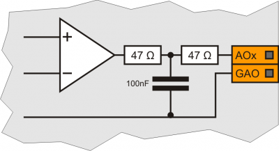
Electrical Characteristics
The electrical characteristics of the hardware are given below.
The maximum and minimum frequencies, and real acquisition times, may depend on eventual additional software filters, for example see the system variable “QMOVE:sys004” at paragraph System Variables.
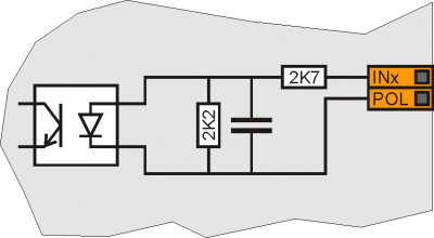
| Type of polarisation | PNP |
| Min. acquisition time (hardware) | 3ms |
| Isolation | 1000Vrms |
| Rated operating voltage | 24Vdc |
| Voltage of logic state 0 | 0-2 V |
| Voltage of logic state 1 | 10.5 - 26.5 V |
| Internal voltage drop | 5V |
| Input resistance (Ri) | 2700Ω |
| Sink current | 2mA ÷ 8mA1) |
1)
CAUTION: If the device connected to the inputs needs a higher minimum current, inputs may not work properly.
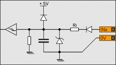
| Type of polarisation | NPN / PNP |
| Max. frequency | 200KHz |
| Min. acquisition time (hardware) | 5µs |
| Insulation | 1000Vrms |
| Rated operating voltage | 24Vdc |
| Voltage of logic status 0 | 0-2 V |
| Voltage of logic status 1 | 10.5 - 26.5 V |
| Internal voltage drop | 1.2 V |
| Input resistance | 2700Ω |
The values given in the table refer to input signals A, B and Z.
The max. frequency given in the table refers to A and B phase signals with a DutyCycle = 50%
With count frequencies over 50KHz the use of Line-Driver type encoders is recommended.
| Type of polarisation | PNP/PP |
| Max frequency | 200KHz |
| Min. acquisition time | 5µs |
| Insulation | 1000Vrms |
| Rated operating voltage | 24Vdc |
| Voltage of logic status 0 | 0 - 2 V |
| Voltage of logic status 1 | 10.5 - 26.5 V |
| Internal voltage drop | 1.2V |
| Input resistance | 3100Ω |
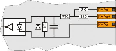
Line-Driver
| Type of polarisation | Line-Driver |
| Max. frequency | 200KHz |
| Min. acquisition time | 5µs |
| Insulation | 1000Vrms |
| Rated operating voltage (PHx+ ? PHx-) | 5Vdc |
| Voltage of logic status 0 (PHx+ ? PHx-) | 0-1.5 V |
| Voltage of logic status 1 (PHx+ ? PHx-) | 2-5 V |
| Internal voltage drop | 1.2V |
| Input restistance | 150Ω |
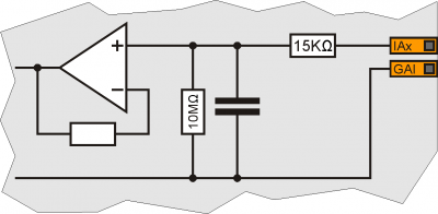
| Type of connection | Potentiometric 1KΩ-20KΩ |
| Resolution | 12bit/16bit |
| Reference voltage output | 2.5Vdc |
| Max output current from reference | 10mA |
| Input resistance | 10MΩ |
| Max. linearity error | + 0,1% Vfs |
| Max. offset error | + 0,1% Vfs |
| S.n. | 71 dB |
| Update speed | 1ms |
| Insulation | 1000 Vrms |
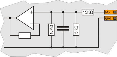
| Type of connection | Voltmetric 0-10V |
| Resolution | 12bit/16bit |
| Input resistance (Rin) | 20KΩ |
| Damage value | 20V |
| Max. linearity error | + 0.1% Vfs |
| Max. offset error | + 0.1% Vfs |
| S.n. | 71 dB |
| Update speed | 1ms |
| Insulation | 1000 Vrms |
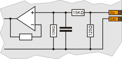
| Type of connection | Amperometric (0-20 mA) |
| Resolution | 12bit/16bit |
| Input resistance | 125Ω |
| Damage value | 25 mA |
| Max. linearity error | + 0,1% Vfs |
| Max. offset error | + 0,1% Vfs |
| S.n. | 71 dB |
| Update speed | 1ms |
| Insulation | 1000 Vrms |
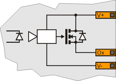
| Switchable load | Dc (PNP) |
| Max. operating voltage | 28V |
| Insulation | 1000Vpp |
| Max. internal voltage drop | 600mV |
| Max internal resistance @ON | 90mΩ |
| Max. protection current | 12A |
| Max. operating current | 2A |
| Max. current @OFF | 5µA |
| Max switching time from ON to OFF | 270µs |
| Max switching time from OFF to ON | 250µs |
| Type of polarisation | Push-Pull / Line-Driver |
| Max output frequency | 50KHz |
| Insulation | 1000Vpp |
| Max. operating current | 20mA |
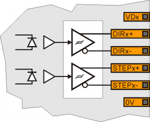
| Type of connection | Common mode |
| Insulation | 1000Vrms |
| Voltage range (minimum no load) | -9.8V - +9.8V |
| Max. offset variation depending on temperature* | +/- 5mV |
| Resolution | 16bit |
| Max. current | 1mA |
| Output variation depending on load | 100 µV/mA |
| Output resistence | 249Ω |
