DEVICE ANINP
1. Introduction
-
The device handles the reading and processing of an analog input.
-
The read data is a word to 16-bit signed which you can add an offset, enter a scaling factor and activate a low-pass RC filter type software.
-
Input resolution specifications are listed in the file adapter hardware.
Wiring and connections of the equipment described in this manual, must comply the European standard EN60204-1.
 | Note: Input resolution specification are reporter in the hardware dossier with the describing the card (or tool). |
|---|
1.1 Installation
1.1.1 Device declaration in the configuration unit
In the configuration unit, the BUS section must be declared must be declared so that they are
present the hardware resources required for the implementation of the ANINP device. Must be present
at least one analog input with a maximum resolution of 16 bits.
In the INTDEVICE section of the configuration unit to add the following definition:
;---------------------------------
; Devices declaration
;---------------------------------
INTDEVICE
...
<nome device>  ANINP  Tcamp  IChn  Type
dove:
| <nome device> | Device name |
| NINP | Keyword that identifies the device analog input |
| Tcamp | Time sampling device (1÷255 ms) |
| IChn | input address ADC |
| Type | ID number input type (refer to technical data sheet hardware) |
 | Warning: It is necessary that each definition are present on the same line. |
|---|
1.1.2 Example
;---------------------------------
; Device declaration
;---------------------------------
INTDEVICE
AnSensor    ANINP 2   2.AI01 1
1.2 Operation
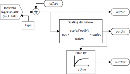
When the system is powered, the device checks the correct input type declaration use the configuration defined in the unit (Type). If the channel diagnostics ends successfully, data is upgraded on the basis of the time of sampling. NIf errors or inaccuracies are found, the st_errcfgState is set to one and the value of the variableoutbitis forced to zero. The conversion of the data output from the device (outbit), in the measure unit required for the application, is activated by means of scale factors (scaleA, scaleB e scaleC) in accordance with the formula:
outUm = (scaleA x outbit / scaleB) + scaleC
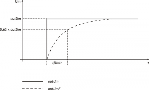
In addition to this updated release based on the sample time of the device, is available the outUmF exit, filtered using a charging time tfilter programmable (expressed in ms).
| This feature allows to filter any disturbances and fluctuations superimposed to the wanted signal with the ability to customize the time of Office of the filter charge (tfilter). |
|---|
1.2.1 Configuration
A single input can be managed by multiple device ANINP simultaneously, provided that the identification number of the Type entrance, inserted in the device declaration is not less; otherwise the analog input is configured as the last device declared in the configuration file.
1.3 Commands and parameters
1.3.1 Symbols used
The parameter name, condition or command is taken back to the left side of the table.
R
Indicates if its parameter or retentive state (upon initialization of the device
maintains state previously defined), or the State that bears upon
device initialization.
If the device does not require initialization field ' R ' indicates the value that the parameter or State
accept to the card power ON.
R = Retentive
0 = Upon initialization of the device the value is forced to zero.
1 = Upon initialization of the device the value is forced to one.
- = Upon initialization of the device is presented significant value.
D
Indicates the parameter size.
F = Flag
B = Byte
W = Word
L = Long
S = Single Float
1.3.1.1 Conditions
Describes all of the conditions that is considered correct or because the command is accepted.
In some cases, limit values are specified for the acceptance of the parameter: If you
any values outside the limits set, the data will still be accepted; must
be provided appropriate controls of the application to ensure proper operation.
To run a command, all the conditions must be
met; otherwise the command is not executed.
A
Access mode.
R = Read.
W = Write.
RW = Read / Write.
1.4 Parameters table
| NAME | D | R | A | Conditions | Description |
|---|---|---|---|---|---|
| outbit | W | - | R | No | Output measure in bits Value read by the input channel offset the Offset. Valid range: 0 ÷ 32767 |
| offset | W | R | RW | No | Offset compensation Offset DAC output in bits. Defines the value in bits of the correction on the analog input in order to compensate for any drift in the system. Valid range: -32768 ÷ 32767 |
| scaleA | W | R | RW | No | Scale A Integer A parameter to scaling formula. Valid range: -32768 ÷ 32767 |
| scaleB | W | R | RW | No | Scale B B parameter value used in the formula of scaling. Must be nonzero. Valid range: -32768 ÷ 32767 |
| scaleC | W | R | RW | No | Scale C C parameter value used in the formula of scaling. Valid range: -32768 ÷ 32767 |
| outUm | L | - | R | No | Output measure in unity Exit derived from scaling formula. Valid range: -32768 ÷ 32767 |
| tfilter | W | R | RW | No | Filter time Charging time of RC filter. If filter < = Tcamp device, the filter is disable. Value expressed in ms. Valid range: 0 ÷ 32767 |
| outUmF | L | - | R | No | Filtered output in unity of measure Output filtered in units. Valid range: -32768 ÷ 32767 |
1.5 States table
| NAME | D | R | A | Conditions | |
|---|---|---|---|---|---|
| st_errcfg | F | - | R | No | Configuration error ignals that an error was detected in the input configuration. 0 = There was no error. 1 = An error was detected. |
1.6 Limitations
1.6.1 Scaling
ScaleB deve essere impostato diverso da zero, in caso contrario OutUm viene forzato a 0.
1.6.2 Filter
The charging time of RC filtertfilter must be set greater than or equal to the time of sampling (Tcamp) device, otherwise, it disables the filter and the OutUmF parameter is updated with the same value as OutUm.
1.6.3 Offset
The offset parameter is added to the acquired analog input (outbit), don't execute the check on the overflow sum.
1.6.4 Configuration
| In the case that a single channel is managed by multiple ANINP with different Type device, the compiler does not detect errors and the channel is set with the last Type declared. |
|---|
A single hardware resource (each input) can be handled by multiple simultaneously ANINP devices, to the condition that the identification number of the entrance (Type), posted in device declaration (configuration file), is the same; otherwise the analog input is configured as the last device declared in the configuration file.
1.7 Application example
1.7.1 Configuration Unit
;*************************************************************************************
; Module Name: Ex_Aninp.CNF                 Project: Ex_ANINP
; Autore: QEM srl                           Date : 01/05/99
; Sistem: QMove1 / QCL3                     Library: 1LIB3B04
; Functionality: ANINP management example   Release: 0
;------------------------------------- Note ------------------------------------------
; [1] - ANINP device application example
;*************************************************************************************
;-------------------------------------------------------------------------------------
; Constants Definition
;-------------------------------------------------------------------------------------
CONST
;-------------------------------------------------------------------------------------
; SYSTEM Variables Definition
;-------------------------------------------------------------------------------------
SYSTEM
slSet1   L                                ;Setpoint 1
slSet2   L                                ;Setpoint 2
;-------------------------------------------------------------------------------------
; GLOBAL Variables Definition
;-------------------------------------------------------------------------------------
GLOBAL
;-------------------------------------------------------------------------------------
; TIMER Variables Definition
;-------------------------------------------------------------------------------------
TIMER
;-------------------------------------------------------------------------------------
; DATAGROUP Definition
;-------------------------------------------------------------------------------------
DATAGROUP

;-------------------------------------------------------------------------------------;
 Bus Configuration
;-------------------------------------------------------------------------------------
BUS
    1   1CPUB   02
    2   1AI8B   00
    3   1MIXA   00
    4   .

;-------------------------------------------------------------------------------------
; INPUT Variables Definition
;-------------------------------------------------------------------------------------
INPUT

;-------------------------------------------------------------------------------------
; OUTPUT Variables Definition
;-------------------------------------------------------------------------------------
OUTPUT
ofGTSet1   F   3.OUT01                    ;Setpoint 1-> Overcoming signal
ofLTSet2   F   3.OUT02                    ;Setpoint 2<- Overcoming signal

;-------------------------------------------------------------------------------------
; Internal Device Declaration
;-------------------------------------------------------------------------------------
INTDEVICE
;Name   Type   TCamp   Counter  Type
Asse    ANINP  0004    2.AI01 2

END
1.7.2 ANINP Management
;*************************************************************************************
; File Name: TASK_00.MOD
; Project: EX_ANINP
; Description: Positioning Management
;*************************************************************************************

;-------------------------------------------------------------------------------------
; Initialization Work Axis
;-------------------------------------------------------------------------------------
Axis:offset = 0                                ;Offset voltage

;-------------------------------------------------------------------------------------
; Scale Factor: (scaleA * outbit / scaleB) + scaleC
; outUm min. = (4 * 0 / 8 ) + 3 = 3
; outUm max. = (4 * 4095 / 8) + 3 = 2050
;-------------------------------------------------------------------------------------
Axis:scaleA = 4                                ;Scale A factor
Axis:scaleB = 8                                ;Scale B factor
Axis:scaleC = 3                                ;Scale C factor
Axis:tfilter = 10                              ;Capture filter time

IF slSet1 EQ 0
 slSet1 = 1500
ENDIF
IF slSet2 EQ 0
 slSet2 = 300
ENDIF
;-------------------------------------------------------------------------------------
; Comparisons on analogue input
;-------------------------------------------------------------------------------------
; Used Variables
; slSet1 : Share of output comparison ofGTSet1 (setting with Qview)
; slSet2 : Share of output comparison ofLTSet2 (setting with Qview)
;-------------------------------------------------------------------------------------

MAIN:
  IF Asse:outUmF GT slSet1                     ;If the analog input is > of the 1 setpoint
    SETOUT ofGTSet1                            ;Activates ofGTSet1 output
  ELSE
    RESOUT ofGTSet1                            ;Disables the ofGTSet1 output
  ENDIF

  IF Asse:outUmF LT slSet2                     ;If the analog input is < of the 2 setpoint 2
    SETOUT ofLTSet2                            ;Activates ofLTSet2 output
  ELSE
    RESOUT ofLTSet2                            ;Disables the ofLTSet2 output
  ENDIF

  WAIT 1
  JUMP MAIN

END