THE DAC DEVICE
1. Introduction
The DAC device is used to manage an analog output with +/- 10V and a 16bit resolution. Its main characteristics:
-
setting in bit of the voltage to generate in output
-
setting an offset to the output voltage
-
setting a minimum and maximum limit to the output voltage
-
inversion of the output voltage value sign
1.1 Declaration of the device
The INTDEVICE section in the configuration unit must have the declaratopm pf the hardware resources needed to use the DAC device. At least one analog output must be present. In the INTDEVICE section of the configuration unit the following definition must be added:
;---------------------------------
; Device definitions
;---------------------------------
INTDEVICE
<device name>  DAC  <IOutA>
where:
| Field name | Description | Example | Notes |
|---|---|---|---|
| <device name> | Nome assegnato al device. | AnOut | |
| DAC | Keyword identifying the analog output device | ||
| <IOutA> | Hardware address of the DAC component of the analog output | 3.AN01 |
 | Unlike other devices, the DAC device does not need a sampling time since it merely converts the input data and updates the output only when the data is entered. |
|---|
Example
;---------------------------------
; Devices definitions
;---------------------------------
INTDEVICE
AnOut DAC  2.AN01
1.2 Execution Description
Block chart of the device:
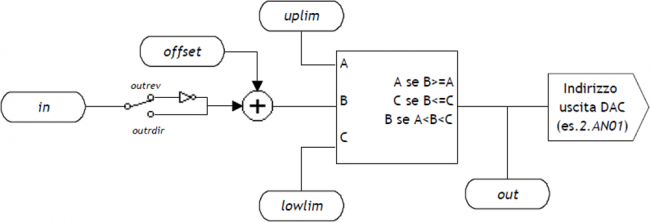
The DAC device, since it works with 16 bit resolution, accepts input values between -32768 and 32767. The output voltage is proportional to the value entered by the user. The device has a symmetrical behaviour around the zero analog voltage at less than any offset value entered. The minimum and maximum analog voltages can be set by the lowlim and uplim parameters, always remaining within ±10V:
-
32767 –> +10 V (maximum permitted),
-
-32768 –> -10 V (minimum permitted).
The value introduced in the device to obtain an analog voltage VOUT is calculated by the proportion:
-
for positive values: in = (VOUT * 32767) / 10,
-
for negative values: in = (VOUT * 32768) / 10.
1.2.1 List of Parameters
1.2.1.1 in
| Short description | Input DAC |
|---|---|
| Dimension | Word |
| Default value | Retentive |
| Access type | Read - Write |
| Unit measure | - |
| Valid range | -32768-32767 |
| Parameter ID | - |
| Write conditions | - |
Description:
Parameter that allows to select the voltage in output from the DAC, which must be between -32768 to 32767. To obtain an analog voltage, VOUT, the following parameter calculation is used:
-
for positive values: in = (VOUT * 32767) / 10,
-
for negative values: in = (VOUT * 32768) / 10.
1.2.1.2 offset
| Short description | Output offset |
|---|---|
| Dimension | Word |
| Default value | Retentive |
| Access type | Read - Write |
| Unit measure | - |
| Valid range | -32768-32767 |
| Parameter ID | - |
| Write conditions | - |
Description:
Offset of the analog output. This parameter defines the correction on the analog output. It is entered in whole values between -32768 and 32767 and the usual calculation is used to obtain a value in Volts.
1.2.1.3 uplim
| Short description | Maximum output voltage |
|---|---|
| Dimension | Word |
| Default value | Retentive |
| Access type | Read - Write |
| Unit measure | - |
| Valid range | -32768-32767 |
| Parameter ID | - |
| Write conditions | - |
Description:
This parameter indicates the maximum output voltage from the device. If the value calculated by the DAC is over uplim this is forced to the parameter value. The value entered can be positive or negative with whole values between -32768 and 32767. To obtain a value in Volts the usual calculation is used.
1.2.1.4 lowlim
| Short description | Minimum output voltage |
|---|---|
| Dimension | Word |
| Default value | Retentive |
| Access type | Read - Write |
| Unit measure | - |
| Valid range | -32768-32767 |
| Parameter ID | - |
| Write conditions | - |
Description:
This parameter indicates the minimum voltage output from the device. If the value calculated by the DAC exceeds lowlim this is forced to the parameter value. The value entered can be either positive or negative with whole values between -32768 and 32767. To obtain a value in Volts the usual proportion is used.
1.2.1.5 out
| Short description | Output DAC |
|---|---|
| Dimension | Word |
| Default value | Retentive |
| Access type | Read |
| Unit measure | - |
| Valid range | lowlim-uplim |
| Parameter ID | - |
| Write conditions | - |
Description:
Parameter that expresses the voltage output of the DAC. The value viewed is the algebric sum of parameter value settings and offset. If the value exceeds the limits set by uplim and lowlim, out is forced to the pre-set maximum or minimum value. This parameter is also expressed in whole values between -32768 and 32767 that are converted in Volts by the usual calculation.
1.2.2 Status List
1.2.2.1 st_lowlim
| Short description | Output voltage status under minimum limit |
|---|---|
| Default value | Retentive |
| Status ID | - |
Description
The status signals the output voltage is under the lower limit. The device has calculated a voltage value beyond the limit set by lowlim and the lowlim value has therefore been forced on the output:
-
0: output voltage in the lower limit,
-
1: output voltage under the lower limit.
1.2.2.2 st_uplim
| Short description | Output voltage status over maximum limit |
|---|---|
| Default value | Ritentivo |
| Status ID | - |
Description
The status signals the output voltage is over the maximum limit. The device has calculated a voltage value beyond the limit set by uplim and the uplim value has therefore been forced on the output:
-
0: output voltage in upper limit,
-
1: output voltage over the upper limit.
1.2.2.3 st_outrev
| Short description | Inversion status of output voltage value sign |
|---|---|
| Default value | Retentive |
| Status ID | - |
Description
The status, after the OUTREV command, signals the output voltage value has changed sign.
1.2.3 List of Commands
The commands provided to manage the device are listed below: the device executes the commands in the order they are received.
1.2.3.1 OUTREV
| Short description | Inversion of output voltage sign. |
|---|---|
| Condition | - |
| Default value | |
| Command ID | - |
Description
The output voltage value sign is inverted
1.2.3.2 OUTDIR
| Short description | Reset output voltage sign. |
|---|---|
| Condition | - |
| Default value | |
| Command ID | - |
Description
The output voltage value sign is reset
1.3 Application Example
This section gives an abstract of code lines as an example in the first steps of using the device in question. As explained, the first step is to declare the device in the configuration unit. Then a new QCL unit can be created for writing the the code to command the controller. The code lines and comments below are examples of some simple operations executed by the device.
1.3.1 Configuration Unit
[...]
BUS
    1   1K31F   30
    2   .       .
    3   1MG8F   .
    4   .

INPUT
  ifChangeOut F 3.INP01 ;Output voltage change command

INTDEVICE
  AnalogOut DAC 3.AN01
1.3.2 Unit QCL
SYSTEM
  slOutAna    L IN         ;Variable for analog output

GLOBAL
  gfChange    F         ;Rise edge flag

BEGIN
  ; Initializations
  AnalogOut.offset = 0
  AnalogOut.uplim = 32767      ;Max analog output as 10V
  AnalogOut.lowlim = -32768    ;Min analog output as -10V
  AnalogOut.OUTDIR             ;Set the right analog output sign
  WAIT NOT AnalogOut.st_outrev ;WAIT the right state
  slOutAna = 0                 ;Set the variable as 0V
MAIN:
  IF ifChangeOut
    IF NOT gfChange;Wait for input activation
      gfChange= 1 ;Set the change made flag
      AnalogOut.in = (slOutAna * AnalogOut.uplim) /100 ;Set the device analog output
    ENDIF
  ELSE
    gfChange = 0 ;Reset the change made flag
  ENDIF

  WAIT 1
  JUMP MAIN

END
When the ifChangeOut input is activated, on the rise front, the output voltage value is updated by the declared DAC device (here named AnalogOut). The voltage value in tenths of a volt is contained in the slOutAna variable. Another unit in the project can access the slOutAna variable and set the required value.