DC10Winding
D = Device(camming2, camming3, camming4)
C = Calculation functions
The DC10Winding function executes the calculations required to construct a cam that manages a wire-guides).
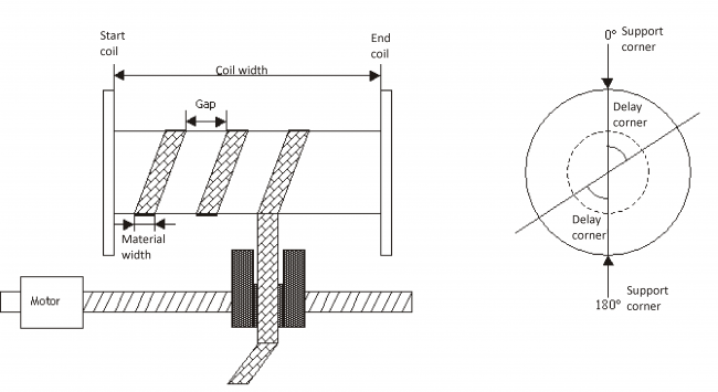
A winding machine consists of two electrically controlled axes and bound together by a Master/Slave relationship. The function is responsible for calculating the cam that operates the Slave axis, the wire-guides, that is an analog axis controlled by Qmove and operated by a Camming device type. This axis has the task of wrapping of rigid material, constantly checking the position of the axis controlled by it (the wire-guides) respect to the rotation of the coil.
The function calculates the areas of the cam program and writes about special arrays, then it will be another function (WrCam) to write data to the device that you want.
N.B.: The Master resolution (measurem and pulsem parameters of camming device) must have a value such that 1 coil round wrap-material corresponds to a value on the counting (positm variable of the camming device) of 360 Units of Measure if the selected unit of measure is in degrees (paramater aslParam[7] = 0), or to 3600 if the selected unit of measure is in tenths of a degree (parameter aslParam [7] = 1), etc..
IMPLEMENTATION
DC10Winding (aslParam, CodeG, CodeM, CodeQm, CodeQs, CodeQsa, NumSett, Error)
The parameters to pass to the function are all contained in an array of 10 elements (called aslParam in the example) in the order described in the following table.
Parameters:
| IN/OUT | VARIABLE TYPE | EXAMPLE NAME | DIM | |
|---|---|---|---|---|
| IN | ARRSYS | aslParam [1] | L | Coil Width (UM Slave) |
| IN | ARRSYS | aslParam [2] | L | Material width (UM Slave) |
| IN | ARRSYS | aslParam [3] | L | Minimum Gap (minimum distance between a deposit of material and the other) (UM Slave) |
| IN | ARRSYS | aslParam [4] | L | Mode of operation (0÷4) (see the chapter) |
| IN | ARRSYS | aslParam [5] | L | Number of support points (0÷9) (see the chapter) |
| IN | ARRSYS | aslParam [6] | L | Corner of delay (0°÷359°) (expressed in degrees) (see the chapter) |
| IN | ARRSYS | aslParam [7] | L | Master unit of measure (Coiler) 0 = degrees 1 = tenths of a degree 2 = hundredths of degree 3 = thousandths of a degree |
| IN | ARRSYS | aslParam [8] | L | Used only in the case of operating mode = 4.\\This parameter must contain the result of the expression: 'current count of the Slave' - (minus) 'count of the Slave to start coil' (UM Slave) |
| IN | ARRSYS | aslParam [9] | L | Used only in the case of operating mode = 4. Master counter (positm) at the time of the cam release (UM Master) |
| IN | ARRSYS | aslParam [10] | L | Used only in the case of operating mode = 4. codeMex value of the camming device at the time of the cam release |
| OUT | ARRSYS | CodeG | W/L | Array containing the calculated G Code |
| OUT | ARRSYS | CodeM | W/L | Array containing the calculated M Code |
| OUT | ARRSYS | CodeQm | L | Array containing calculated Master Space |
| OUT | ARRSYS | CodeQs | L | Array containing calculated Slave Space |
| OUT | ARRSYS | CodeQsa | L | Array containing the auxiliary Slave Space |
| OUT | SYSTEM | NumSett | L | Calculated cam Sectors number (output variable) |
| OUT | SYSTEM | sbError | B | Error variable (see Error chapter) |
Mode of operation
How discriminates as starts to work the wire-guides. In particular:
0 = From the start Coil
1 = From the end Coil
2 = From half-way forward
3 = From half-way backward
4 = Reboot from a stop cam. In this case, you must also set the aslParam[8], aslParam[9] and aslParam[10] parameters.
Support points
For the distribution of the coil there is a theory, called 'THEORY OF SUPPORT POINTS', which agree that reversing the movement of the wire-guides must occur at particular points, to ensure that the coil do not disassemble. You may have 2, 3, 4 support points depending on whether the reverse position is 1/2, 1/3, 1/4 the round angle. Also there are for the 3 and 4 support points, 4 different possibilities and for 2 support points 2 possibilities. The type and number of support points you discriminate with aslParam[5] parameter as follows:
2 Support points:
0 = angles 90° - 180°
1 = angles 270° - 540°
3 Support points:
2 = angles 60° - 120°
3 = angles 120° - 240°
4 = angles 240° - 480°
5 = angles 300° - 600°
4 Support points:
6 = angles 45° - 90°
7 = angles 135° - 270°
8 = angles 225° - 450°
9 = angles 315° - 630°
For example, if the parameter is set to 0 (zero) means that the coil to the first distribution will do a whole number of laps plus 90°, to returns, will accomplish the same number of laps plus 90° coming back to the initial position but staggered 180°. The next pass will arrive with a phase shift of 270° and upon returning with a phase shift of 360°. In practice the reverse movement of the wire-guides will be, on one side, always on 180° and to 0°, on the other side, always 90° and to 270° causing the gap ever in two fixed points.
The situation is similar with the parameter set to 1: the coil will make a whole number of laps plus 270° to the first distribution, the return will accomplish the same number of laps plus 270° take back to 180° (270°+270°= 540°= 180°).
The operation of the theory is similar to the 3 and 4 support points Recalling that the phase shift between the support points of the same side will be respectively 120° and 90° instead of 180°.
Corner of delay
The delay angle indicates the space, expressed in degrees of angle round, in which the Slave axis (the wire-guides) should remain stationary at the start and end of the coil after arriving on the leaning angle.
CodeM
The M code (array CodeM of the the parameters table) is the array that makes sure that dynamics phase of the cam, the “codeMex” parameter of the device takes certain values based on the stretch of cam that is covering. In particular when codeMex vale:
0 = Axis stopped
1 = Axis moving forward
2 = Axis moving backward
3 = Axis in delay angle of the final part of the spool
4 = Axis in delay angle of the initial part of the spool
Error
After calling the function, if there are any errors the error variable takes certain values, the meaning of these values is summarized below:
0 : calculation executed without errors
1 : Delay angle off limits
2 : Master units off limits
3 : Support angle off limits
4 : Distance between Slave and coil end off limits
5 : Material width off limits
6 : Cam not achievable (negative Master space)
7 : Introduced Master count off limits
8 : codeMex value off limits
Wire-guide diagram
Operation notes
-
This function always calculates the cam dividing it into 7 sectors
-
If, during operation, the speed of the Master exceeds the set value as reference speed (“VriferM” parameter) the good operation of the cam is no longer guaranteed (the analog output of the slave could go into saturation)