1. P1R11FA10 - 001 : Connections
1.1 Informations
Release
This document is fully valid, except for errors or omissions.
| Release | Description | Date |
|---|---|---|
| 1.0 | New manual. | 15/07/16 |
| 1.0b | Upgrade points 1.2 and 2.0 on the user manual | 02/09/16 |
Specifications
All rights reserved on this manual. No part of this document can be copied or reproduced in any form without prior written authorisation .
QEM does not insure or guarantee its contents and explicitly declines all liability related to the guarantee of its suitability for any purpose. The information provided in this document can be changed without notice. QEM shall not be held liable for any error that may appear in this document.
Registered Trademarks:
-
QEM® is a registered trademark.
-
Microsoft® and MS-DOS® are registered trademarks and Windows® is a trademark of Microsoft Corporation.
1.2 Description
The P1R11FA10 - 001 application, installed on the Qmove C1-R11-FA10 hardware, it is the Modbus/RTU Slave gateway to the QEM HA548.04 instrument.
Follow we report the main features of the P1R11FA10 - 001 software.
1.3 Hardware and connections
1.3.1 Main board
1.3.1.1 Power supply
The instrument will need to be supplied with 24Vdc. Isn't necessary the internal fuse.
1.3.1.2 Connectivity
-
PROG PORT → TTL logic standard serial port for programming.
-
USER PORT → Multistandard (RS232, RS422, RS485) port for MODBUS/RTU Slave.
-
PORTA AUX RS485 → RS485 port for HB548.04 connection.
Nr. 1 MMC card reader for saving/storing from external memory.
1.3.1.3 C1-R11
 |
| C1-R11 front view |
1.4 Electrical connections
1.4.1 C1-R11
1.4.1.1 CN1- Power supply (power input)
| Power supply type | 24 Vdc | 24 Vac |
|---|---|---|
| Valid range | 22 ÷ 27 Vdc | +/-15% |
| Max. absorption | 30W | 35VA |
| Frequency | 50/60Hz |
 | 1 | AC phase / positive DC terminal |
| 2 | Ground | |
| 3 | AC phase / 0V DC terminal |
CN2 - USER PORT. RS232-RS422-RS485 serial (insulated)
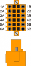 | 1A | A – RS485 MODBUS/RTU Slave |
| 2A | B – RS485 MODBUS/RTU Slave | |
| 3A | 0V - Serial port common. | |
| 4A | 0V - Serial port common. | |
| 5A | TX (Transmission RS232) | |
| 6A | PE - Ground. | |
| 1B | RX - (Receive “positive” RS422) | |
| 2B | RXN - (Receive “negative” RS422) | |
| 3B | TX - (Transmission “positive” RS422) | |
| 4B | TXN - (Transmission “negative” RS422) | |
| 5B | RX (Riceive RS232) | |
| 6B | PE - Ground. |
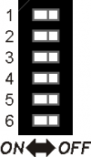
 | NB. The DIP SW2 group under the serial port must be set with ONLY THE 5 DIP = ON. |
|---|
1.4.1.1.1 USER PORT settings
1.4.2 PROG PORT and USER PORT Baud-rate selector
| SW1 | Dip | DIP setting | Function | |||
|---|---|---|---|---|---|---|
 | 1 | OFF | OFF | ON | ON | PROG PORT speed selection of transmission |
| 2 | OFF | ON | OFF | ON | ||
| Baud-rate 38400 | Baud-rate 115200 | Baud-rate 19200 | Baud-rate 57600 |
|||
| 3 | OFF | OFF | ON | ON | USER PORT speed selection of transmission | |
| 4 | OFF | ON | OFF | ON | ||
| Baud-rate 38400 | Baud-rate 115200 | Baud-rate 19200 | Baud-rate 57600 |
|||
| 5 | CANbus baud-rate selector. | |||||
| 6 | OFF | ON | PROG PORT mode of operation selection | |||
| PROG PORT can be used by SERCOM and MODBUS device | PROG PORT can't be used by SERCOM and MODBUS device | |||||
| 7 | CANbus baud-rate selector. | |||||
| 8 | OFF | ON | Set the USER PORT as PROG PORT1) | |||
| Normal PROG PORT | PROG PORT on the USER PORT connector | |||||
1.4.3 AUX2 PORT
| CN4 | Terminal | Simbol | Description |
|---|---|---|---|
 | 1 | 0V | RS485 serial common |
| 2 | B | RS485 B terminal - to connect at the terminal number 2 of the DB9-M connector of the HA548.04 | |
| 3 | A | Terminale RS485 A - to connect at terminal number 8 of the DB9-M connector of the HA548.04 |
| SW4 | Num. Dip | Name Dip | Setting dei DIP | Function |
|---|---|---|---|---|
 | 1 | JP3 | ON | Polarizer RS485 |
| 2 | JP2 | ON | Termination RS485 | |
| 3 | JP1 | ON | Polarizer RS485 | |
| 4 | X1) | none |
| You must enable the AUX2 PORT polarizer and termination resistors |
|---|