Quick Start Guide J1-P20-Fx

Informations
| |
|||
| Document: | QSGJ1P20Fx_EN01 | ||
|---|---|---|---|
| Description: | J1-P20-Fx Quick Start Guide | ||
| Drawn up by: | Riccardo Furlato | ||
| Approved by: | Gabriele Bazzi | ||
| Link: | http://www.qem.eu/doku/doku.php/en/strumenti/qmoveplus/j1P20/qsgj1P20fx_en01 | ||
| Language: | English | ||
| Release | Description | Note | Data |
| 01 | New manual | 07/16/2015 | |
This QUICK START GUIDE provides all the information necessary to:
-
Verify the characteristics of the purchased product
-
Make a correct installation and fixing
-
Verify the basic operation
For more information please read the Installation and Maintenance manual, that can be found online at http://www.qem.eu/doku/doku.php/en/strumenti/qmoveplus/j1P20
The controller has been designed for industral environments in conformity to EC directive 2004/108/CE.
-
EN 61000-6-4: Electromagnetic compatibility - Generic standard on emission for industrial environments
-
EN55011 Class A: Limits and measurement methods
-
EN 61000-6-2: Electromagnetic compatibility - Generic standard on immunity for industrial environments
-
EN 61000-4-2: Electromagnetic compatibility - Electrostatic discharge immunity
-
EN 61000-4-3: Immunity to radiated, radio-frequency electromagnetic field
-
EN 61000-4-4: Electrical fast transients
-
EN 61000-4-5: Surge immunity
-
EN 61000-4-6: Conducted disturbance induced by radio-frequency
-
Moreover the product is conform to the following standards:
-
EN 60529: Housing protection rating IP64
-
EN 60068-2-1: Environmental testing: Cold
-
EN 60068-2-2: Environmental testing: Dry heat
-
EN 60068-2-14: Environmental testing: Change of temperature
-
EN 60068-2-30: Environmental testing: Cyclic damp heat
-
EN 60068-2-6: Environmental testing: Sinusoidal vibration
-
EN 60068-2-27: Environmental testing: Shock vibration
-
EN 60068-2-64: Environmental testing: Random vibration
-

1. Description
J1-P20-F is a combo HMI-PAC controller of the Qmove+ range.
1.1 Product Identificaiton

The Product Ordering Code provides its exact characteristics.
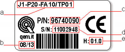
Verify that the product characteristics comply with your requirements.1.1.1 Product Label
-
a - Ordering Code
-
b - Week made: indicates the week and year of manufacture
-
c - Part number: unique code that identifies an ordering code
-
d - Serial number: product serial number, different for individual product
-
e - Hardware release: version of hardware release
1.1.2 Ordering Code
Model Caratteristics J1 - P20 - FA - 10 / TP01 TP00 = Keypad Code (TP00 = pannel with resistive touchscreen , custom logo and function keys);
TP01 = panel with resistive touchscreen, Qem standard logo and function keys
10 = Firmware version (00 = not installed) F = Technological level
A = Hardware versionP = Only function keys
2 = 5“ LCD graphic display, TFT display-256 COLOUR-800x480px; front panel size (168x144mm); keypad 7 keys + 11 led; housing to DIN 43700;
0 = Firmware-hardware correspondenceJ1 = “HMI+PLC” Qmove family
1.1.3 Hardware Versions
These are the currently hardware versions available:
Versioni hardware A B C D E F G H I J K L M N P W Y Z Base
cardUSER PORT (RS232-422-485) - - - - - - - 1 - 1 - - - - - 1 1 1 CAN PORT - - - 1 1 1 1 1 1 1 1 1 - 1 - 1 1 1 ETHERNET PORT - - - - - - - 1 1 - 1 1 1 1 1 1 1 1 Standard digital inputs 16 16 16 16 16 16 16 16 16 16 16 16 16 16 16 - 16 16 Fast digital inputs (also designed for use as frequency meters) - 2 2 - 2 2 2 2 - - 2 2 - - 2 - 2 2 Two-way count inputs, 200KHz ABZ (24V-PP, 5V-LD) - 2 2 - 2 2 2 2 - - 2 2 - - 2 - 2 2 Protected digital outputs 16 16 16 16 16 16 16 16 16 16 16 16 16 16 16 - 16 16 0-10V-12bit analog outputs - - - - - - - - - - - - - - - - - - +/-10V-16bit analog outputs - - 2 - - 2 - 2 - - - 2 - - 2 - 2 2 Card software code declared as base card 1MD1F Expansion
cardStandard digital inputs - - - - - - 8 8 - - - - 8 8 - - - 8 12bit analog inputs - - - - - - - - - - - - - - - - - 16bit selectable analog inputs(0-10V, 0-20mA, potenz, thermocouples, PT100) - - - - - - - - - - - 2 - - - - - 2 Protected digital outputs - - - - - - 8 8 - - - - 8 8 - - - 8 0-10V-12bit analog outputs - - - - - - - - - - - - - - - - - - +/-10V-16bit analog outputs - - - - - - - - - - - - - - - - - - AUX PORT (RS485) - - - - - - - - - - - - - - - - - - Expansion card software code declared in SLOT 3 - - - - - - 
- - - - - -
1.1.4 Expansion card manuals
1.1.5 Firmware versions
Version Description 10 Fully programmable with PLC functions 20 Fully programmable with PLC and Motion control functions 30 Fully programmable with PLC, Motion control, Camming and Interpolation functions For more details about the firmware, consult Devices enabled in the controllers.
2. Technical Characteristics
2.1 General Characteristics
Weight (full hardware) 1Kg Housing Sheet metal Front panel Aluminium Outer Frame Self-extinguishing Noryl Display LCD 5'' TFT 256 colori - 800 x 480px Touch screen 4-wire Resistive Display dimensions 108 x 64,8mm / 5“ User led's 7 System led's 4 Function keys 7 System keys 3 Operating temperature 0 ÷ 50°C Transport and storage temperature -25 ÷ +70 °C Relative humidity 90% condensate free Altitude 0 - 2000m a.s.l. Front protection rating IP64 2.2 CPU (F technology)
RISC Miscroprocessor (32 bit) Work Frequency 200MHz RAM 8MB Flash 8MB
2.3 Dimensions

Dimensions in mm. 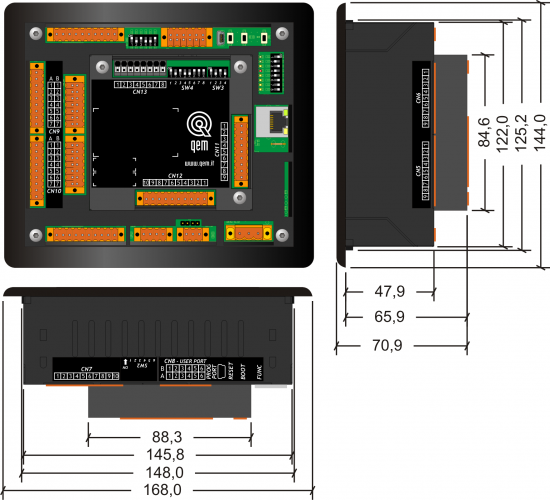
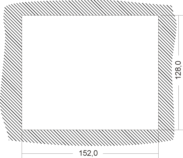
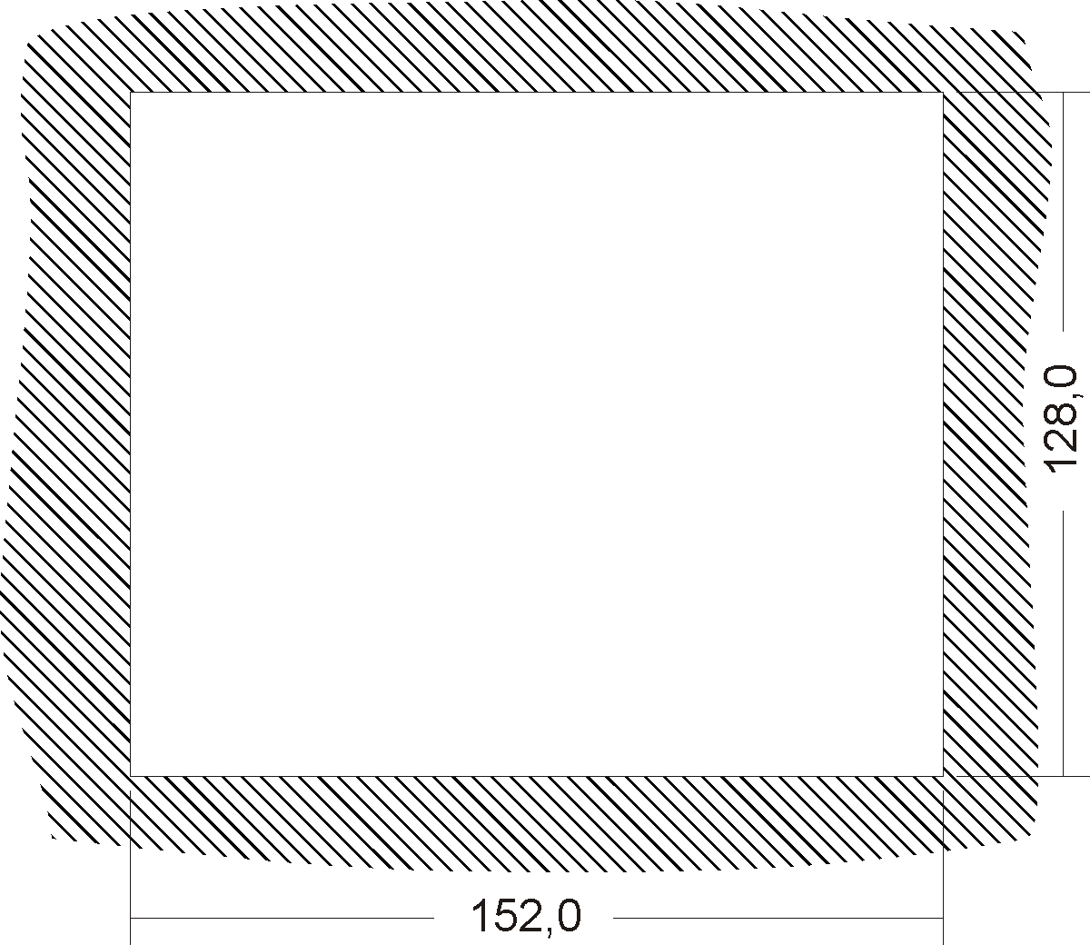
2.4 Hole template
2.5 Installation
Fit the controller in the hole.

Apply the brackets.
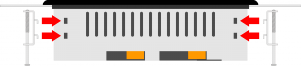

Before fixing the controller, check it is mounted firmly in the hole and the gasket under the frame makes a good seal. No liquids must enter and the frame must not deform. Screw the controller in place.
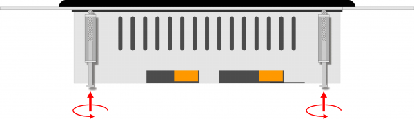
Warning: after putting the pin of fixing, do only half rotation to not tear the frame!
3. Base card connections
Per informazioni riguardanti le sezioni dei cavi utilizabili ed i connettori usati, consultare l'application note AN021 3.1 Power supply

The cabling must be carried out by specialist personnel and fitted with suitable anti-static precautions.
Before handling the controller, disconnect the power and all parts connected to it.
To guarantee compliance with EC regulations, the power supply must have a galvanic isolation of at least 1500Vac..
Power supply 24 Vdc Voltage range 22 - 27 Vdc Max. absorption 10W Connector
CN1 Terminal Symbol Description 

1 
DC power positive 2 GROUND Gnd-PE (signals) 3 
DC power 0V Connection examples
Use an isolated power unit with 24Vdc +/-5% output conform to EN60950-1. .
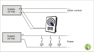
Use two separate power units: one for the control circuit and one for the power circuit 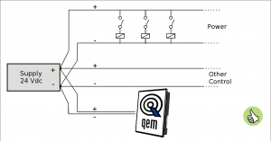
For a single power unit, use two separate lines: one for the control and one for the power 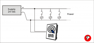
DO NOT use the same lines for the power circuit and the controller
4. Verify the basic operation
After you have correctly connected the instrument to the power line, as mentioned above, you can proceed with the power up.
In the powering up, the Leds are scanned:
the 8 LED light up sequentially on the rear of the instrument (pow, run, stop, err, L1, L2, L3 and L4).

Self-diagnostics
After scanning of the leds, the device performs a series of diagnostic operations.
When the anomalies are detected or when is need to notify at the operator a particular situation, the autodiagnosis operation is momentarily interrupted, and the device pointing out the alarm.
Any malfunction is stand out from the L1, L2 leds and a display message.
If the device is working properly, at the end of the stages of switching on self-diagnostics, you may encounter the following situations:
-
led pow in ON (CPU in RESET state)
-
led pow and run in ON (CPU in RUN state)
-
led pow in ON and the run in flashing(CPU in READY state)
5. Assistance
For supplying you fast service, at the lowest cost, we need your support.


Follow all instructions provided in the MIMAT manual If the problem remains, fill out the “Request Form for assistance” on the page Contacts at www.qem.it site.
Our technicians will get elements essential for the understanding of your problem.Repair
To provide you with an efficient service, please read and adhere to the instructions given here
Shipping
It is recommended to pack the instrument with materials that are able to cushion any falls.


Use the original package: it must protect the instrument during transport. Attach:
1. A description of the anomaly;
2. A part of the electric scheme where the equipment is inserted
3. The planning of the equipment (set up, quotas of job, parameters…).
4. Request a quote for repair; if not required, the cost will be calculated in the final balance.A full description of the problem, will help identify and resolve your problems fast. A careful packaging will avoid further inconveniences. 
Printing only the pages you need will reduce paper consumption -
-


- Last modified: 2019/08/29 17:01