P1P51FD30 - 001 : Connections and Setup
1. Information
Release
This document is fully valid except for errors and ommissions.
| Release | Description | Date |
|---|---|---|
| 1.0 | New manual | 29/03/12 |
2. Description
The P1P51FD30 - 001 application, installed on the Qmove J1-P51-FD30 hardware, is designed to control a bundling machine. The main
characteristics of the P1P51FD30 - 001 software are provided below.
In this document great attention has been made to distinguish between standard characteristics that are readily available and characteristics for future and optional developments.
Characteristics implemented in this hardware and software version
-
Control of 2 analog axes
-
Touch-screen functionalities for data entry and mechanical function keys
-
Operator support messages
-
Alarm messages
-
Semi-automatic commands
-
Management of partial piece and hour counters
3. Hardware and connections
Base card
Power unit
The controller must be supply by 24Vdc. There is no built-in fuse.
Connectivity
The “standard version” has 2 serial ports:
-
PROG PORT → Serial port with TTL logic standard for programming.
-
USER PORT → Multistandard serial port (RS232, RS422, RS485).
-
CAN PORT → Canbus type “field bus”.
1 MMC slot for data saving/loading from external mass storage.
J1-P51-FD30
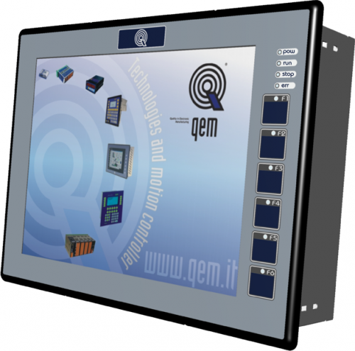 |
| J1-P51FD30 with standard QEM film |
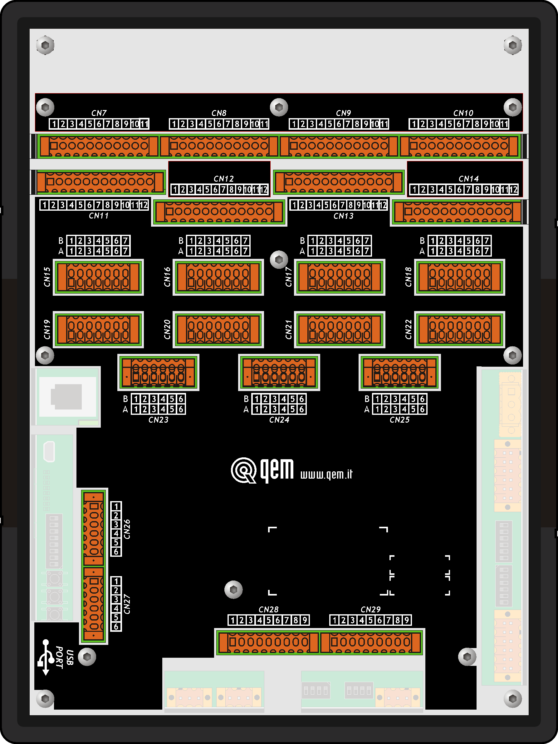 |
| Rear view of J1-P51FD30 |
I/O List
This section will list the I/O's used, divided by connector. For more details on the I/O's, see below where each connector is described.
Digital inputs (n. 32)
| NAME | DESCRIPTION | TERMINAL | HARDWARE |
|---|---|---|---|
| I1 | Emergency Stop Emerjans | CN11 | J1P51-FD30 |
| I2 | Housing - Door 1 Kapi 1 |
||
| I3 | Housing - Door 2 Kapi 2 |
||
| I4 | Housing - Door 3 Kapi 3 |
||
| I5 | Housing - Door 4 Kapi 4 |
||
| I6 | Film Feed Driver Fault Servo 1 Fault |
||
| I7 | Film Cut Driver Fault Servo 2 Fault |
||
| I8 | Infeed Conveyor Inverter Fault Giris Band motor Ariza |
||
| I9 | Main Conveyor Inverter Fault Ana Tahrik motor Ariza | CN12 | J1P51-FD30 |
| I10 | Outfeed Conveyor Inverter Fault Cikis Band motor Ariza |
||
| I11 | Cardboard Present Photocell Karton gorme fotocell |
||
| I12 | Material Infeed Photocell Giris Band motor fotocell |
||
| I13 | Material Photocell Bayrak fotocell |
||
| I14 | Outfeed Fallen Material Photocell Cikis Sise dustu fotocell |
||
| I15 | No Film Photocell Film Bitti fotocell |
||
| I16 | Start Bundling Cycle Photocell Naylon verici fotocell |
||
| I17 | Film Slack Photocell (brake lock) Naylon gergi fotocell | CN13 | J1P51-FD30 |
| I18 | Camme Zero-set Photocell Encoder Sifirlama fotocell |
||
| I19 | Broken Film Photocell Nylon Tasiyici kopuk fotocell |
||
| I20 | Doors Open Kapirlar acik |
||
| I21 | Infeed Fallen Material Control Photocell Giris Sise dusme fotocell |
||
| I22 | Stop Button Stop buton |
||
| I23 | Not used | ||
| I24 | Not used | ||
| I25 | Not used | CN14 | J1P51-FD30 |
| I26 | Not used | ||
| I27 | Not used | ||
| I28 | Not used | ||
| I29 | Not used | ||
| I30 | Not used | ||
| I31 | Not used | ||
| I32 | Not used |
Fast inputs (n. 1)
| NAME | DESCRIPTION | TERMINAL | HARDWARE |
|---|---|---|---|
| I03 | Film spot photocell Mark Okuyucu fotocell | CN13 | J1P51-FD30 |
Digital outputs (n. 32)
| NAME | DESCRIPTION | TERMINAL | HARDWARE |
|---|---|---|---|
| O1 | Infeed Conveyor START command Giris Band motor start | CN7 | J1P51-FD30 |
| O2 | Main Conveyor START command Ana Tahrik motor start |
||
| O3 | Outfeed Conveyor START command Cikis Band motor start |
||
| O4 | Vacuum Pump solenoid valve Vakum salyangoz motor |
||
| O5 | Red signal light Kirmizi alarm lambasi |
||
| O6 | Green signal light Yesil alarm lambasi |
||
| O7 | Separator 1 gate solenoid vale Seperator 1 |
||
| O8 | Separator 2 gate solenoid valve Seperator 2 |
||
| O9 | Reel cylinder brake Film solenoid | CN8 | J1P51-FD30 |
| O10 | Driver reset Servo reset |
||
| O11 | “Sarsak” solenoid valve Sarsak |
||
| O12 | External Start machine consensus Mak. giris konver feetback |
||
| O13 | Not used | ||
| O14 | Not used | ||
| O15 | Not used | ||
| O16 | Not used | ||
| O17 | Not used | CN9 | J1P51-FD30 |
| O18 | Not used | ||
| O19 | Not used | ||
| O20 | Not used | ||
| O21 | Not used | ||
| O22 | Not used | ||
| O23 | Not used | ||
| O24 | Not used | ||
| O24 | Not used | ||
| O25 | Not used | CN10 | J1P51-FD30 |
| O26 | Not used | ||
| O27 | Not used | ||
| O28 | Not used | ||
| O29 | Not used | ||
| O30 | Not used | ||
| O31 | Not used | ||
| O32 | Not used |
Two-way count inputs (n° 4)
| Name | Description | Connector | Hardware |
|---|---|---|---|
| PHA1 PHB1 | Main Conveyor encoder Encoder Besleme | CN15 | J1P51-FD30 |
| PHA2 PHB2 | Film Feed encoder Naylon Servo | CN16 | |
| PHA3 PHB3 | Film Cut encoder Bicak Servo | CN17 | |
| PHA4 PHB4 | Not used | CN18 |
Analog inputs (n. 4)
| Name | Description | Connector | Hardware |
|---|---|---|---|
| AI1 | Not used | CN28 | J1P51-FD30 |
| AI2 | Not used | ||
| AI3 | Not used | CN29 | |
| AI4 | Not used |
Analog outputs (n. 8)
| Name | Description | Connector | Hardware |
|---|---|---|---|
| AO1 | 0-10Vdc reference Infeed Conveyor 0-10Vdc Analog Giris Band motor | CN26 | J1P51-FD30 |
| AO2 | 0-10Vdc reference Main Conveyor 0-10Vdc Analog Ana Tahrik motor |
||
| AO3 | 0-10Vdc reference Outfeed Conveyor 0-10Vdc Analog Cikis Band motor |
||
| AO4 | Not used | ||
| AO5 | +/-10Vdc reference Film Feed +/-10Vdc Analog Naylon surme motor | CN27 | J1P51-FD30 |
| AO6 | +/-10Vdc Film Cut 0-10Vdc Analog Bicak motor |
||
| AO7 | Not used | ||
| AO8 | Not used |
Function keys
| Name | Description | Hardware |
|---|---|---|
| F1 | To decide | J1P51-FD30 |
| F2 | To decide | |
| F3 | To decide | |
| F4 | To decide | |
| F5 | To decide | |
| F6 | To decide |
4. Electrical Connections
 | The cabling must be carried out by specialist personnel and fitted with suitable anti-static precautions. Before handling the controller, disconnect the power and all parts connected to it. To guarantee compliance with EC regulations, the power supply must have a galvanic isolation of at least 1500Vac. |
|---|
| Power supply | 24 Vdc |
|---|---|
| Voltage range | 22 - 27 Vdc |
| Max. absorption | 30W |
| CN1 | Terminal | Symbol | Description |
|---|---|---|---|
  | 1 | L1/+ | DC power positive |
| 2 | GROUND | Gnd-PE (signals) | |
| 3 | L2/- | DC power 0V |
Connection examples for 24Vdc power supply
| Use an isolated power unit with 24Vdc +/-5% output conform to EN60950-1. |
|---|
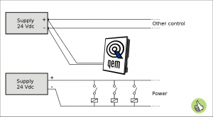 | Use two separate power units: one for the control circuit and one for the power circuit |
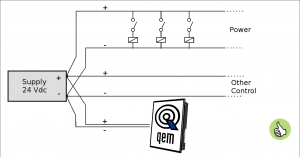 | For a single power unit, use two separate lines: one for the control and one for the power |
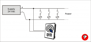 | DO NOT use the same lines for the power circuit and the controller |
 | The electrical features are given in paragraph Electrical Features. The wiring examples are given in paragraph Connection examples |
|---|
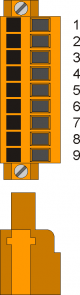
| CN11 | Terminal | Symbol | Description | Address | |
|---|---|---|---|---|---|
 | 1 | I01(PNP) | PNP type fast input I01 | External terminal configuration1) | FREQ12) |
| 2 | I01(NPN) | PNP type fast input I01 | |||
| 3 | 0V | Common for digital inputs | |||
| 4 | I1 | Input I1 | 3.INP01 | ||
| 5 | I2 | Input I2 | 3.INP02 | ||
| 6 | I3 | Input I3 | 3.INP03 | ||
| 7 | I4 | Input I4 | 3.INP04 | ||
| 8 | I5 | Input I5 | 3.INP05 | ||
| 9 | I6 | Input I6 | 3.INP06 | ||
| 10 | I7 | Input I7 | 3.INP07 | ||
| 11 | I8 | Input I8 | 3.INP08 | ||
| 12 | 0V | Common for digital inputs | |||
| CN12 | Terminal | Symbol | Description | Address | |
|---|---|---|---|---|---|
| | 1 | I02(PNP) | PNP type fast input I02 | External terminal configuration1) | FREQ22) |
| 2 | I02(NPN) | NPN type fast input I02 | |||
| 3 | 0V | Common for digital inputs | |||
| 4 | I9 | Input I9 | 3.INP09 | ||
| 5 | I10 | Input I10 | 3.INP10 | ||
| 6 | I11 | Input I11 | 3.INP11 | ||
| 7 | I12 | Input I12 | 3.INP12 | ||
| 8 | I13 | Input I13 | 3.INP13 | ||
| 9 | I14 | Input I14 | 3.INP14 | ||
| 10 | I15 | Input I15 | 3.INP15 | ||
| 11 | I16 | Input I16 | 3.INP16 | ||
| 12 | 0V | Common for digital inputs | |||
| CN13 | Terminal | Symbol | Description | Address | |
|---|---|---|---|---|---|
| | 1 | I03(PNP) | PNP type fast input I03 | External terminal configuration1) | 1.INT09 |
| 2 | I03(NPN) | NPN type fast input I03 | |||
| 3 | 0V | Common for digital inputs | |||
| 4 | I17 | Input I17 | 3.INP17 | ||
| 5 | I18 | Input I18 | 3.INP18 | ||
| 6 | I19 | Input I19 | 3.INP19 | ||
| 7 | I20 | Input I20 | 3.INP20 | ||
| 8 | I21 | Input I21 | 3.INP21 | ||
| 9 | I22 | Input I22 | 3.INP22 | ||
| 10 | I23 | Input I23 | 3.INP23 | ||
| 11 | I24 | Input I24 | 3.INP24 | ||
| 12 | 0V | Common for digital inputs | |||
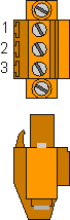
Terminal 1: connect to 12-24Vdc of the power unit
Terminal 2: input
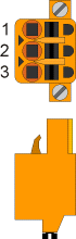
PNP type fast input configuration:
Terminal 1: input
Terminal 2: connect to 0V (terminal 3)
| CN14 | Terminal | Symbol | Description | Address | |
|---|---|---|---|---|---|
| | 1 | I04(PNP) | PNP type fast input I04 | External terminal configuration1) | 1.INT10 |
| 2 | I04(NPN) | NPN type fast input I04 | |||
| 3 | 0V | Common for digital inputs | |||
| 4 | I25 | Input I25 | 3.INP25 | ||
| 5 | I26 | Input I26 | 3.INP26 | ||
| 6 | I27 | Input I27 | 3.INP27 | ||
| 7 | I28 | Input I28 | 3.INP28 | ||
| 8 | I29 | Input I29 | 3.INP29 | ||
| 9 | I30 | Input I30 | 3.INP30 | ||
| 10 | I31 | Input I31 | 3.INP31 | ||
| 11 | I32 | Input I32 | 3.INP32 | ||
| 12 | 0V | Common for digital inputs | |||
Terminal 1: connect to 12-24Vdc of the power unit
Terminal 2: input
PNP type fast input configuration:
Terminal 1: input
Terminal 2: connect to 0V (terminal 3)
| The electrical features are given in paragraph Electrical features. The connection examples are given in paragraph Connection examples |
|---|
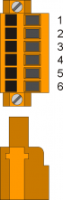
| CN7 | Terminal | Symbol | Description | Address |
|---|---|---|---|---|
 | 1 | V+ | Output supply in (12÷28Vdc) | |
| 2 | O1 | Digital output 1 | 3.OUT01 | |
| 3 | O2 | Digital output 2 | 3.OUT02 | |
| 4 | V- | Common for output supply | ||
| 5 | O3 | Digital output 3 | 3.OUT03 | |
| 6 | O4 | Digital output 4 | 3.OUT04 | |
| 7 | V- | Common for output supply | ||
| 8 | O5 | Digital output 5 | 3.OUT05 | |
| 9 | O6 | Digital output 6 | 3.OUT06 | |
| 10 | O7 | Digital output 7 | 3.OUT07 | |
| 11 | O8 | Digital output 8 | 3.OUT08 |
| CN8 | Terminal | Symbol | Description | Address |
|---|---|---|---|---|
| | 1 | V+ | Output supply in (12-28Vdc) | |
| 2 | O9 | Digital output 9 | 3.OUT09 | |
| 3 | O10 | Digital output 10 | 3.OUT10 | |
| 4 | V- | Common for output supply | ||
| 5 | O11 | Digital output 11 | 3.OUT11 | |
| 6 | O12 | Digital output 12 | 3.OUT12 | |
| 7 | V- | Common for output supply | ||
| 8 | O13 | Digital output 13 | 3.OUT13 | |
| 9 | O14 | Digital output 14 | 3.OUT14 | |
| 10 | O15 | Digital output 15 | 3.OUT15 | |
| 11 | O16 | Digital output 16 | 3.OUT16 |
| CN9 | Terminal | Symbol | Description | Address |
|---|---|---|---|---|
| | 1 | V+ | Output supply in (12-28Vdc) | |
| 2 | O17 | Digital output 17 | 3.OUT17 | |
| 3 | O18 | Digital output 18 | 3.OUT18 | |
| 4 | V- | Common for output supply | ||
| 5 | O19 | Digital output 19 | 3.OUT19 | |
| 6 | O20 | Digital output 20 | 3.OUT20 | |
| 7 | V- | Common for output supply | ||
| 8 | O21 | Digital output 21 | 3.OUT21 | |
| 9 | O22 | Digital output 22 | 3.OUT22 | |
| 10 | O23 | Digital output 23 | 3.OUT23 | |
| 11 | O24 | Digital output 24 | 3.OUT24 |
| CN10 | Terminal | Symbol | Description | Address |
|---|---|---|---|---|
| | 1 | V+ | Output supply in (12-28Vdc) | |
| 2 | O25 | Digital output 25 | 3.OUT25 | |
| 3 | O26 | Digital output 26 | 3.OUT26 | |
| 4 | V- | Common for output supply | ||
| 5 | O27 | Digital output 27 | 3.OUT27 | |
| 6 | O28 | Digital output 28 | 3.OUT28 | |
| 7 | V- | Common for output supply | ||
| 8 | O29 | Digital output 29 | 3.OUT29 | |
| 9 | O30 | Digital output 30 | 3.OUT30 | |
| 10 | O31 | Digital output 31 | 3.OUT31 | |
| 11 | O32 | Digital output 32 | 3.OUT32 |
| The electrical features are given in paragraph Electrical features. The wiring examples are given in paragraph Connection examples |
|---|
| CN15 | Terminal | Symbol | Description | Address | ||
|---|---|---|---|---|---|---|
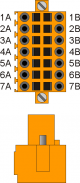 | 1A | Internal bridge 1A -1B 1) | ||||
| 2A | PHA1 | Phase A | Count 1 PNP Push-Pull2) | 3.INP33 | 3.CNT01 | |
| 3A | PHB1 | Phase B | 3.INP34 | |||
| 4A | Z1 | Z | 1.INT01 | |||
| 5A | 0V | Common for count inputs | ||||
| 6A | 0V | |||||
| 7A | 0V | |||||
| 1B | Internal bridge 1A -1B3) | |||||
| 2B | PHA1+ | + PHA | Count 1 Line Driver | 3.INP33 | 3.CNT01 | |
| 3B | PHB1+ | + PHB | 3.INP34 | |||
| 4B | Z1+ | + Z | 1.INT01 | |||
| 5B | PHA1- | - PHA | ||||
| 6B | PHB1- | - PHB | ||||
| 7B | Z1- | - Z | ||||
Terminal 5B: connect to terminal 5A
Terminal 6B: connect to terminal 6A
Terminal 7B: connect to terminal 7A
| CN16 | Terminal | Symbol | Description | Address | ||
|---|---|---|---|---|---|---|
| | 1A | Internal bridge 1A -1B 1) | ||||
| 2A | PHA2 | Phase A | Count 2 PNP Push-Pull2) | 3.INP35 | 3.CNT02 | |
| 3A | PHB2 | Phase B | 3.INP36 | |||
| 4A | Z2 | Z | 1.INT02 | |||
| 5A | 0V | Common for count inputs | ||||
| 6A | 0V | |||||
| 7A | 0V | |||||
| 1B | Internal bridge 1A -1B3) | |||||
| 2B | PHA2+ | + PHA | Count 2 Line Driver | 3.INP35 | 3.CNT02 | |
| 3B | PHB2+ | + PHB | 3.INP36 | |||
| 4B | Z2+ | + Z | 1.INT02 | |||
| 5B | PHA2- | - PHA | ||||
| 6B | PHB2- | - PHB | ||||
| 7B | Z2- | - Z | ||||
Terminal 5B: connect to terminal 5A
Terminal 6B: connect to terminal 6A
Terminal 7B: connect to terminal 7A
| CN17 | Terminal | Symbol | Description | Address | ||
|---|---|---|---|---|---|---|
| | 1A | Internal bridge 1A -1B 1) | ||||
| 2A | PHA3 | Phase A | Count 3 PNP Push-Pull2) | 3.INP37 | 3.CNT03 | |
| 3A | PHB3 | Phase B | 3.INP38 | |||
| 4A | Z3 | Z | 1.INT03 | |||
| 5A | 0V | Common for count inputs | ||||
| 6A | 0V | |||||
| 7A | 0V | |||||
| 1B | Internal bridge 1A -1B3) | |||||
| 2B | PHA3+ | + PHA | Count 3 Line Driver | 3.INP37 | 3.CNT03 | |
| 3B | PHB3+ | + PHB | 3.INP38 | |||
| 4B | Z3+ | + Z | 1.INT03 | |||
| 5B | PHA3- | - PHA | ||||
| 6B | PHB3- | - PHB | ||||
| 7B | Z3- | - Z | ||||
Terminal 5B: connect to terminal 5A
Terminal 6B: connect to terminal 6A
Terminal 7B: connect to terminal 7A
| CN18 | Terminal | Symbol | Description | Address | ||
|---|---|---|---|---|---|---|
| | 1A | Internal bridge 1A -1B 1) | ||||
| 2A | PHA4 | Phase A | Count 4 PNP Push-Pull2) | 3.INP39 | 3.CNT04 | |
| 3A | PHB4 | Phase B | 3.INP40 | |||
| 4A | Z4 | Z | 1.INT04 | |||
| 5A | 0V | Common for count inputs | ||||
| 6A | 0V | |||||
| 7A | 0V | |||||
| 1B | Internal bridge 1A -1B3) | |||||
| 2B | PHA4+ | + PHA | Count 4 Line Driver | 3.INP39 | 3.CNT04 | |
| 3B | PHB4+ | + PHB | 3.INP40 | |||
| 4B | Z4+ | + Z | 1.INT04 | |||
| 5B | PHA4- | - PHA | ||||
| 6B | PHB4- | - PHB | ||||
| 7B | Z4- | - Z | ||||
Terminal 5B: connect to terminal 5A
Terminal 6B: connect to terminal 6A
Terminal 7B: connect to terminal 7A
| CN19 | Terminal | Symbol | Description | Address | ||
|---|---|---|---|---|---|---|
| | 1A | Internal bridge 1A -1B 1) | ||||
| 2A | PHA5 | Phase A | Count 5 PNP Push-Pull2) | 3.INP41 | 3.CNT05 | |
| 3A | PHB5 | Phase B | 3.INP42 | |||
| 4A | Z5 | Z | 1.INT05 | |||
| 5A | 0V | Common for count inputs | ||||
| 6A | 0V | |||||
| 7A | 0V | |||||
| 1B | Internal bridge 1A -1B3) | |||||
| 2B | PHA5+ | + PHA | Count 5 Line Driver | 3.INP41 | 3.CNT05 | |
| 3B | PHB5+ | + PHB | 3.INP42 | |||
| 4B | Z5+ | + Z | 1.INT05 | |||
| 5B | PHA5- | - PHA | ||||
| 6B | PHB5- | - PHB | ||||
| 7B | Z5- | - Z | ||||
Terminal 5B: connect to terminal 5A
Terminal 6B: connect to terminal 6A
Terminal 7B: connect to terminal 7A
| CN20 | Terminal | Symbol | Description | Address | ||
|---|---|---|---|---|---|---|
| | 1A | Internal bridge 1A -1B 1) | ||||
| 2A | PHA6 | Phase A | Count 6 PNP Push-Pull2) | 3.INP43 | 3.CNT06 | |
| 3A | PHB6 | Phase B | 3.INP44 | |||
| 4A | Z6 | Z | 1.INT06 | |||
| 5A | 0V | Common for count inputs | ||||
| 6A | 0V | |||||
| 7A | 0V | |||||
| 1B | Internal bridge 1A -1B3) | |||||
| 2B | PHA6+ | + PHA | Count 6 Line Driver | 3.INP43 | 3.CNT06 | |
| 3B | PHB6+ | + PHB | 3.INP44 | |||
| 4B | Z6+ | + Z | 1.INT06 | |||
| 5B | PHA6- | - PHA | ||||
| 6B | PHB6- | - PHB | ||||
| 7B | Z6- | - Z | ||||
Terminal 5B: connect to terminal 5A
Terminal 6B: connect to terminal 6A
Terminal 7B: connect to terminal 7A
| CN21 | Terminal | Symbol | Description | Address | ||
|---|---|---|---|---|---|---|
| | 1A | Internal bridge 1A -1B 1) | ||||
| 2A | PHA7 | Phase A | Count 7 PNP Push-Pull2) | 3.INP45 | 3.CNT07 | |
| 3A | PHB7 | Phase B | 3.INP46 | |||
| 4A | Z7 | Z | 1.INT07 | |||
| 5A | 0V | Common for count inputs | ||||
| 6A | 0V | |||||
| 7A | 0V | |||||
| 1B | Internal bridge 1A -1B3) | |||||
| 2B | PHA7+ | + PHA | Count 7 Line Driver | 3.INP45 | 3.CNT07 | |
| 3B | PHB7+ | + PHB | 3.INP46 | |||
| 4B | Z7+ | + Z | 1.INT07 | |||
| 5B | PHA7- | - PHA | ||||
| 6B | PHB7- | - PHB | ||||
| 7B | Z7- | - Z | ||||
Terminal 5B: connect to terminal 5A
Terminal 6B: connect to terminal 6A
Terminal 7B: connect to terminal 7A
| CN22 | Terminal | Symbol | Description | Address | ||
|---|---|---|---|---|---|---|
| | 1A | Internal bridge 1A -1B 1) | ||||
| 2A | PHA8 | Phase A | Count 8 PNP Push-Pull2) | 3.INP47 | 3.CNT08 | |
| 3A | PHB8 | Phase B | 3.INP48 | |||
| 4A | Z8 | Z | 1.INT08 | |||
| 5A | 0V | Common for count inputs | ||||
| 6A | 0V | |||||
| 7A | 0V | |||||
| 1B | Internal bridge 1A -1B3) | |||||
| 2B | PHA8+ | + PHA | Count 8 Line Driver | 3.INP47 | 3.CNT08 | |
| 3B | PHB8+ | + PHB | 3.INP48 | |||
| 4B | Z8+ | + Z | 1.INT08 | |||
| 5B | PHA8- | - PHA | ||||
| 6B | PHB8- | - PHB | ||||
| 7B | Z8- | - Z | ||||
Terminal 5B: connect to terminal 5A
Terminal 6B: connect to terminal 6A
Terminal 7B: connect to terminal 7A
| The electrical features are given in paragraph Electrical features. The wiring examples are given in paragraph Connection examples |
|---|
| CN28 | Terminal | Symbol | Description | Address |
|---|---|---|---|---|
 | 1 | GAI | Common for analog inputs | |
| 2 | IA1 | analog input 1 | 3.AI01 | |
| 3 | SEL1V | Analog input selector 1 voltmetric 0-10V1) | ||
| 4 | SEL1C | Analog input selector 1 amperometric 0-20mA2) | ||
| 5 | GAI | Common for analog inputs | ||
| 6 | IA2 | analog input 2 | 3.AI02 | |
| 7 | SEL2V | Analog input selector 2 voltmetric 0-10V3) | ||
| 8 | SEL2C | Analog input selector 2 amperometric 0-20mA4) | ||
| 9 | VREF | Reference voltage |
| CN29 | Terminal | Symbol | Description | Address |
|---|---|---|---|---|
| | 3 | GAI | Common for analog inputs | |
| 2 | IA3 | analog input 3 | 3.AI03 | |
| 3 | SEL3V | Analog input selector 3 voltmetric 0-10V1) | ||
| 4 | SEL3C | Analog input selector 3 amperometric 0-20mA2) | ||
| 5 | GAI | Common for analog inputs | ||
| 6 | IA4 | analog input 4 | 3.AI04 | |
| 7 | SEL4V | Analog input selector 4 voltmetric 0-10V3) | ||
| 8 | SEL4C | Analog input selector 4 amperometric 0-20mA4) | ||
| 9 | VREF | Reference voltage |
| The electrical features are given in paragraph Electrical features. The wiring examples are given in paragraph Connection examples |
|---|
| CN26 | Terminal | Symbol | Description | Address |
|---|---|---|---|---|
 | 1 | GAO | Common for analog outputs | |
| 2 | AO1 | Analog output 1 | 3.AN01 | |
| 3 | AO2 | Analog output 2 | 3.AN02 | |
| 4 | GAO | Common for analog outputs | ||
| 5 | AO3 | Analog output 3 | 3.AN03 | |
| 6 | AO4 | Analog output 4 | 3.AN04 |
| CN27 | Terminal | Symbol | Description | Address |
|---|---|---|---|---|
| | 1 | GAO | Common for analog outputs | |
| 2 | AO5 | Analog output 5 | 3.AN05 | |
| 3 | AO6 | Analog output 6 | 3.AN06 | |
| 4 | GAO | Common for analog outputs | ||
| 5 | AO7 | Analog output 7 | 3.AN07 | |
| 6 | AO8 | Analog output 8 | 3.AN08 |