1. Electrical Connections Manual
2. Information
2.1 Release
| |
|||
| Document: | mce_p1r44f-024 | ||
|---|---|---|---|
| Description: | Electrical connections manual p1r44f-024 | ||
| Editor: | Andrea Zarantonello | ||
| Approver | Giuliano Tognon | ||
| Link: | https://www.qem.eu/doku/doku.php/strumenti/qmoveplus/c1r44/p1r44f-024/mce_p1r44f-024 | ||
| Language: | English | ||
| Release document | Description | Notes | Date |
| 01 | New manual | 16/03/2023 | |
2.2 Specifications
The copyright of this manual is reserved. No part of this document may be copied or reproduced in any form without the prior written authorization of QEM.
QEM makes no representations or warranties regarding the contents and specifically disclaims any warranties of fitness for any particular purpose. The information in this document is subject to change without notice. QEM assumes no responsibility for any errors that may appear in this document.
Registered Trademarks:
-
QEM® is a registered trademark.
3. Hardware and Connections
The device models used for this application are as follows:
-
C1-R44-FF30: motion control CPU unit and automation logic;
-
A1-IPC-TC101-AC/W10: Industrial Panel PC with a 10.1“ display and capacitive touch screen;
-
IQ023/A/USB/50: panel PC input module;
-
RMC-3M B01 MV /I16/I16/I16/I16/A41/24V: Digital inputs + multiple analog inputs module;
-
RMC-3M B01 MZ /A41/A41/A41/A41/0/24V: Multiple analog inputs module;
-
RMC-3M B01 DD /P16/P16/P16/P16/P16/24Vdc: Multiple output module;
3.1 C1-R44-FF30
 |
| Front view of C1-R44 |

| 1MG2F Expansion |
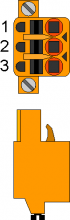
3.1.1 C1-R44: Power Supply
3.1.1.1 C1-R44: CN1
The device must be powered at 24Vdc. Provide an external fuse in series with the positive conductor +24Volt.
| CN1 | Terminal | Symbol | Description | |
|---|---|---|---|---|
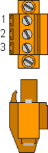 |  | 1 | | Positive power supply |
| 2 | GROUND | Ground-PE (signals) | ||
| 3 | | 0V power supply | ||
3.1.2 Connectivity
-
PROG PORT → Serial with TTL logic standard for programming.
-
USER PORT → Multistandard serial (RS232, RS422, RS485).
-
AUX RS485 PORT → Multistandard serial (RS232, RS422, RS485).
-
ETHERNET PORT → RJ45 Connector
-
CAN PORT → Canbus type “fieldbus.”
3.1.2.1 ETHERNET port
| ETHERNET PORT | Description |
|---|---|
 | Connector RJ45. LED: * LINK: green led = cable connected (led on signals the cable is connected to both ends) * DATA: yellow led = data transmission (flashing led signals data transmission) |
3.1.2.2 PROG PORT and USER PORT baud-rate selector
SET TRANSMISSION SPEED CAN TO 500 KB/S
| SW 1 | Dip | Dip Settings | Function | |||
|---|---|---|---|---|---|---|
 | 1 | OFF | Baud-rate 57600 | Selection of transmission speed PROG PORT | ||
| ON | Baud-rate 115200 | |||||
| 2 | OFF | Baud-rate 57600 | Selection of transmission speed USER PORT | |||
| ON | Baud-rate 115200 | |||||
| 3 | OFF | Usable also by SERCOM and MODBUS devices | Selection of operating mode PROG PORT | |||
| ON | Not usable by SERCOM and MODBUS devices | |||||
| 4 | OFF | ON | OFF | ON | CANbus transmission speed (CanOpen) | |
| 5 | OFF | OFF | ON | ON | ||
| Baud-rate\ 125KB/S | Baud-rate\ 250KB/S | Baud-rate\ 500KB/S | Baud-rate\ 1MB/S | |||
| 6 | OFF | MMC/SD | External media device selection in system functions | |||
| ON | USB | |||||
| 7 | Reserved for internal use. Leave OFF | |||||
| 8 | OFF | Normal PROG PORT | Select USER PORT as PROG PORT | |||
| ON | PROG PORT on USER PORT connector | |||||
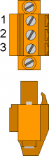
3.1.2.3 C1-R44: CN5 - CAN PORT
| CN5 | Terminal | Symbol | Description |
|---|---|---|---|
 | 1 | 0V | Common CAN |
| 2 | CAN L | CAN L Terminal | |
| 3 | CAN H | CAN H Terminal |
3.1.2.4 Termination Resistor Settings
Check the CAN connection to determine termination resistor activation
| Jumper Name | Setting | Function | |
|---|---|---|---|
JP3 JP4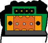 | JP3 | INSERTED | Termination CAN activated |
| JP4 |
3.1.2.5 CAN Cable Connection Example
 The CAN module RMC-3M B01 MZ is only present with the abrasive thickness reading implementation; therefore, the module is optional.
There are two ways to connect:
1st way:

2nd way:

3.1.3 Digital Inputs
| S = State | A = Action | ID |
|---|---|---|
| NO = Normally Open | I = Impulsive | ID = Software |
| NC = Normally Closed | C = Continuous |
3.1.3.1 C1-R44: CN7
| CN 7 | Pin | ID | Description | S | A | |
|---|---|---|---|---|---|---|
 | 1 | 0V | 0 Volt (common inputs I1 ÷ I8 ) | |||
| 2 | I1 | Thermal head | - | NC | C | |
| 3 | I2 | Master Bridge Fault | - | |||
| 4 | I3 | Belt Fault | - | NC | C | |
| 5 | I4 | Roller Fault | - | |||
| 6 | I5 | Air Pressure | - | NC | C | |
| 7 | I6 | Water Pressure | - | |||
| 8 | I7 | Forward Bridge LS | - | |||
| 9 | I8 | Backward Bridge LS | - | |||
3.1.3.1.1 Connection Example

3.1.3.2 C1-R44: CN6
| CN 6 | Pin | ID | Description | S | A | |
|---|---|---|---|---|---|---|
| | 1 | 0V | 0 Volt (common inputs I9 ÷ I16 ) | |||
| 2 | I9 | Master Bridge Zero Sensor | NO | I | ||
| 3 | I10 | Slab Presence Sensor | End of Roller | |||
| 4 | I11 | Start of Belt | ||||
| 5 | I12 | Worn Abrasive Sensor | - | |||
| 6 | I13 | Emergency | - | NC | C | |
| 7 | I14 | Pressurized Lubrication Circuit Feedback | NO | I | ||
| 8 | I15 | External Consent ON | - | NC | C | |
| 9 | I16 | Auxiliary Enable | - | |||
3.1.3.2.1 Connection Example

3.1.3.3 C1-R44: CN18
| CN 18 | Pin | ID | Description | S | A | |
|---|---|---|---|---|---|---|
| | 1 | 0V | 0 Volt (common inputs I9 ÷ I16 ) | |||
| 2 | I17 | N/A | ||||
| 3 | I18 | Bridge Jog | Forward | NO | I | |
| 4 | I19 | Backward | ||||
| 5 | I20 | START | ||||
| 6 | I21 | STOP | ||||
| 7 | I22 | Abrasive Change | ||||
| 8 | I23 | MAN/AUTO | ||||
| 9 | I24 | STAND-BY | ||||
3.1.3.4 C1-R44: CN19
| CN 19 | Pin | ID | Description | S | A | |
|---|---|---|---|---|---|---|
| | 1 | 0V | 0 Volt (common inputs I9 ÷ I16 ) | |||
| 2 | I25 | Slave Bridge Zero Sensor | NO | I | ||
| 3 | I26 | Slave Bridge Fault | NC | C | ||
| 4 | I27 | N/A | ||||
| 5 | I28 | N/A | ||||
| 6 | I29 | N/A | ||||
| 7 | I30 | N/A | ||||
| 8 | I31 | N/A | ||||
| 9 | I32 | N/A | ||||
3.1.4 Digital Outputs
| S = State | ID |
|---|---|
| OFF = Off | ID = Software |
| ON = On |
3.1.4.1 C1-R44: CN9 (Out +24 Volt, 500 mA)
| CN 9 | Pin | ID | Description | S | |
|---|---|---|---|---|---|
 | 1 | V+ | + 24 Volt (common outputs 01 ÷ 04) | ||
| 2 | O1 | ON/OFF master bridge | - | OFF | |
| 3 | O2 | ON/OFF belt | - | ||
| 4 | O3 | ON/OFF rollers | - | ||
| 5 | O4 | Up / Down Brush | - | ||
| 6 | V+ | +24 Volt (common outputs 05 ÷ 08 ) | |||
| 7 | O5 | ON/OFF previous machine | - | OFF | |
| 8 | O6 | Lubrication (optional) | - | ||
| 9 | O7 | Stop Belt | - | ||
| 10 | O8 | Alarm Status | - | ON | |
| 11 | 0V | 0 Volt (common outputs 01 ÷ 08) | |||
3.1.4.1.1 Connection Example

3.1.4.2 C1-R44: CN8 (Out +24 Volt, 500 mA)
| CN 8 | Pin | ID | Description | S |
|---|---|---|---|---|
| | 1 | V+ | +24 Volt (common outputs O09÷O12) | |
| 2 | O09 | ON/OFF slave bridge | OFF | |
| 3 | O10 | Unlock electromechanical locks | OFF | |
| 4 | O11 | Forward belt | OFF | |
| 5 | O12 | Backward belt | OFF | |
| 6 | V+ | +24 Volt (common outputs O13÷O16) | ||
| 7 | O13 | Reset belt drive/inverter | OFF | |
| 8 | O14 | Reset Master Bridge1 drive/inverter | OFF | |
| 9 | O15 | Reset Slave Bridge2 drive/inverter | OFF | |
| 10 | O16 | N/A | - | |
| 11 | 0V | 0 Volt (common outputs O09÷O16) |
3.1.4.3 C1-R44: CN 25 (Out +24 Volt, 500 mA)
| CN 25 | Pin | ID | Description | S |
|---|---|---|---|---|
| | 1 | V+ | +24 Volt (common output) | |
| 2 | O17 | Alarm indicator light | OFF | |
| 3 | O18 | Green light indicator | OFF | |
| 4 | O19 | Yellow light indicator | OFF | |
| 5 | O20 | n.u | ||
| 6 | V+ | +24 Volt (common output) | ||
| 7 | O21 | n.u | ||
| 8 | O22 | n.u | ||
| 9 | O23 | n.u | ||
| 10 | O24 | n.u | ||
| 11 | 0V | 0 Volt (common output) |
3.1.4.4 C1-R44: CN 20 (Out +24 Volt, 500 mA)
| CN 20 | Pin | ID | Description | S |
|---|---|---|---|---|
| | 1 | V+ | +24 Volt (common output) | |
| 2 | O25 | n.u. | ||
| 3 | O26 | n.u. | ||
| 4 | O27 | n.u. | ||
| 5 | O28 | n.u. | ||
| 6 | V+ | +24 Volt (common output) | ||
| 7 | O29 | n.u. | ||
| 8 | O30 | n.u. | ||
| 9 | O31 | n.u. | ||
| 10 | O32 | n.u. | ||
| 11 | 0V | 0 Volt (common output) |
3.1.5 Bidirectional Count Inputs
3.1.5.1 For "Push Pull" Encoder Type
3.1.5.1.1 C1-R44: CN14
| CN 14 (Push Pull) | PIN | ID | Description | |||
|---|---|---|---|---|---|---|
 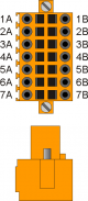 | 1B | +24V IN | Input +24 Volt | Master Bridge Counting | ||
| 1A | +24V OUT | Encoder power supply | Encoder power supply | |||
| 2A | PHA1 | Phase A+ | ||||
| 3A | PHB1 | Phase B+ | ||||
| 4A | - | - | ||||
| 5A | 0V ∩ | Connect to 5B | Common for counting inputs. Internally connected to 0Volt (PIN 3 - CN1) | |||
| 6A | 0V ∩ | Connect to 6B | ||||
| 7A | 0V ∩ | Connect to 7B | ||||
3.1.5.1.2 Connection Example

3.1.5.1.3 C1-R44: CN15
| CN15 (Push Pull) | PIN | ID | Description | COMMENTS | |||
|---|---|---|---|---|---|---|---|
| | 1B | +24V IN | Input +24 Volt | Belt Counting | |||
| 1A | +24V OUT | Output +24 Volt | Encoder power supply | ||||
| 2A | PHA2 | Phase A+ | |||||
| 3A | PHB2 | Phase B+ | |||||
| 4A | - | - | |||||
| 5A | 0V ∩ | Connect to 5B | Common for counting inputs. Internally connected to 0Volt (PIN 3 - CN1) | ||||
| 6A | 0V ∩ | Connect to 6B | |||||
| 7A | 0V ∩ | Connect to 7B |
3.1.5.1.4 Connection Example

Click here for more connection examples
3.1.5.1.5 C1-R44: CN16
| CN 16 (Push Pull) | PIN | ID | DESCRIPTION | COMMENTI | ||
|---|---|---|---|---|---|---|
| | 1B | +24V IN | Input +24 Volt | Bridge slave counting | ||
| 1A | +24V OUT | Output +24 Volt | Encoder power supply | |||
| 2A | PHA3 | Phase A | - | |||
| 3A | PHB3 | Phase B | - | |||
| 4A | - | - | - | |||
| 5A | 0V ∩ | Connect to PIN 5B | Counting inputs common. Internal connected to 0V (PIN 3 - CN1) |
|||
| 6A | 0V ∩ | Connect to PIN 6B | ||||
| 7A | 0V ∩ | Connect to PIN 7B | ||||
3.1.5.1.6 Esempio di collegamento
3.1.5.2 For "Line Driver 24 Volt" Encoder Type
3.1.5.2.1 C1R44: CN14
| CN 14 (Line Driver 24 Volt) | PIN | ID | Description | ||||
|---|---|---|---|---|---|---|---|
| | 1B | +24V IN | Input +24 Volt | Master Bridge Counting | |||
| 1A | +24V OUT | Encoder power supply | |||||
| 2A | PHA1 | Phase A+ | |||||
| 3A | PHB1 | Phase B+ | |||||
| 4A | - | - | |||||
| 5B | PHA1- | Phase A- | |||||
| 6B | PHB1- | Phase B- | |||||
| 7B | - | - | |||||
3.1.5.2.2 Connection Example

3.1.5.2.3 C1R44: CN15
| CN15 (Line Driver 24 Volt) | PIN | ID | DESCRIPTION | |||
|---|---|---|---|---|---|---|
| \ | 1B | +24V IN | Input +24 Volt | Count Tape | ||
| 1A | +24V OUT | Encoder Supply | ||||
| 2A | PHA2 | Phase A+ | ||||
| 3A | PHB2 | Phase B+ | ||||
| 4A | - | - | ||||
| 5B | PHA2- | Phase A- | ||||
| 6B | PHB2- | Phase B- | ||||
| 7B | - | - | ||||
3.1.5.2.4 Wiring Example
 \
\
3.1.5.2.5 C1R44: CN16
| CN 16 (Line Driver 24 Volt) | PIN | ID | DESCRIPTION | |||
|---|---|---|---|---|---|---|
| \ | 1B | +24V IN | Input +24 Volt | Count Bridge Slave | ||
| 1A | +24V OUT | Encoder Supply | ||||
| 2A | PHA3 | Phase A+ | ||||
| 3A | PHB3 | Phase B+ | ||||
| 4A | - | - | ||||
| 5B | PHA3- | Phase A- | ||||
| 6B | PHB3- | Phase B- | ||||
| 7B | - | - | ||||
3.1.5.2.6 Wiring Example
3.1.5.3 For Simulated 5 Volt Line Driver Encoders
3.1.5.3.1 C1R44: CN14
| CN 14 (Simulated 5 Volt Line Driver) | PIN | ID | DESCRIPTION | |||
|---|---|---|---|---|---|---|
| \ | 2B | PHA1+ | Phase A+ | Count Bridge Master | ||
| 3B | PHB1+ | Phase B+ | ||||
| 4B | - | - | ||||
| 5B | PHA1- | Phase A- | ||||
| 6B | PHB1- | Phase B- | ||||
| 7B | - | - | ||||
3.1.5.3.2 Wiring Example

3.1.5.3.3 C1R44: CN15
| CN15 (Simulated 5 Volt Line Driver) | PIN | ID | DESCRIPTION | |||
|---|---|---|---|---|---|---|
| \ | 2B | PHA2+ | Phase A+ | Count Belt | ||
| 3B | PHB2+ | Phase B+ | ||||
| 4B | - | - | ||||
| 5B | PHA2- | Phase A- | ||||
| 6B | PHB2- | Phase B- | ||||
| 7B | - | - | ||||
3.1.5.3.4 Wiring Example

3.1.5.3.5 C1R44: CN16
| CN 16 (Simulated 5 Volt Line Driver) | PIN | ID | DESCRIPTION | |||
|---|---|---|---|---|---|---|
| \ | 2B | PHA3+ | Phase A+ | Count Bridge Slave | ||
| 3B | PHB3+ | Phase B+ | ||||
| 4B | - | - | ||||
| 5B | PHA3- | Phase A- | ||||
| 6B | PHB3- | Phase B- | ||||
| 7B | - | - | ||||
3.1.5.3.6 Wiring Example
3.1.6 Analog Inputs
3.1.6.1 C1-R44: CN13
| CN13 | Terminal | Symbol | Description |
|---|---|---|---|
 | 1 | VREF | Reference voltage 1) |
| 2 | AI1 | n.a. | |
| 3 | AI2 | n.a. | |
| 4 | AI3 | n.a. | |
| 5 | GAI | Common analog inputs |
Configuration of Analog Inputs
| SW4 | Dip No.\ Dip | Analog Input 1 | Analog Input 2 | Analog Input 3 | ||||||
|---|---|---|---|---|---|---|---|---|---|---|
| Pot. | 0-10V | 0-20mA | Pot. | 0-10V | 0-20mA | Pot. | 0-10V | 0-20mA | ||
 | 1 | OFF | OFF | ON | X | X | X | X | X | X |
| 2 | OFF | ON | OFF | X | X | X | X | X | X | |
| 3 | X | X | X | OFF | OFF | ON | X | X | X | |
| 4 | X | X | X | OFF | ON | OFF | X | X | X | |
| 5 | X | X | X | X | X | X | OFF | OFF | ON | |
| 6 | X | X | X | X | X | X | OFF | ON | OFF | |
X = irrelevant setting
Pot. = potentiometric input
0-10V = voltmeter input
0-20mA = amperometric input
3.1.7 Analog Outputs
3.1.7.1 C1-R44: CN12
| CN 12 | Pin | ID | Description |
|---|---|---|---|
 | 1 | GA01 | Common for analog outputs AO1÷AO2 |
| 2 | AO1 | Bridge Master: +/- 10 Volt control | |
| 3 | AO2 | Tape: 0/10 Volt control | |
| 4 | GA02 | Common for analog outputs AO3÷AO4 | |
| 5 | AO3 | Bridge Slave: +/- 10 Volt control | |
| 6 | AO4 | n.a. |
3.1.7.1.1 Wiring Example

3.2 A1-IPC-TC101: Panel PC
3.2.1 A1-IPC-TC101: Panel PC

3.2.1.1 Connection
The Panel PC has two Ethernet lines. The first one connects to the company LAN network, and the second one connects to the R44. Connection to the company LAN network is also possible via WiFi.

3.2.2 IQ023/A/USB/50
IQ023 makes available to the PC 24 digital inputs, 8 analog inputs, and 4 encoder inputs.

3.2.2.1 Power Supply
IQ023 is powered by the 5V from the USB port.
3.2.2.2 Connectors
| A+ | A0 | A1 | A2 | A3 | GND | +5 | E1A | E1B | E2A | E2B | D1 | D2 | D3 | D4 | D5 | D6 | D7 | D8 | D9 | D10 | D11 | D12 | GND |
| . | |||||||||||||||||||||||
 |
|||||||||||||||||||||||
| . | |||||||||||||||||||||||
| A+ | A4 | A5 | A6 | A7 | GND | +5 | E3A | E3B | E4A | E4B | D13 | D14 | D15 | D16 | D17 | D18 | D19 | D20 | D21 | D22 | D23 | D24 | GND |
3.2.2.3 Digital Inputs
| S = Status | A = Action | ID |
|---|---|---|
| NO = Normally Open | I = Impulsive | ID = Software |
| NC = Normally Closed | C = Continuous |
| Pin | ID | Description | S | A | |
|---|---|---|---|---|---|
| D1 | I97 | HEAD UP SELECTOR | Head 1 | NO | I |
| D2 | I98 | Head 2 | |||
| D3 | I99 | Head 3 | |||
| D4 | I100 | Head 4 | |||
| D5 | I101 | Head 5 | |||
| D6 | I102 | Head 6 | |||
| D7 | I103 | Head 7 | |||
| D8 | I104 | Head 8 | |||
| D9 | I105 | Head 9 | |||
| D10 | I106 | Head 10 | |||
| D11 | I107 | Head 11 | |||
| D12 | I108 | Head 12 | |||
| GND | 0 V | 0 Volt | |||
| D13 | I109 | HEAD DOWN SELECTOR | Head 1 | NO | I |
| D14 | I110 | Head 2 | |||
| D15 | I111 | Head 3 | |||
| D16 | I112 | Head 4 | |||
| D17 | I113 | Head 5 | |||
| D18 | I114 | Head 6 | |||
| D19 | I115 | Head 7 | |||
| D20 | I116 | Head 8 | |||
| D21 | I117 | Head 9 | |||
| D22 | I118 | Head 10 | |||
| D23 | I119 | Head 11 | |||
| D24 | I120 | Head 12 | |||
| GND | 0 V | 0 Volt | |||
3.2.2.4 Connection Examples

3.3 RMC-3M B01 DD
 |
| Overview of RMC-3M |
 |
| RMC-3M Bus Composition |
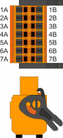
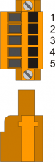
3.3.1 RMC-3M B01 DD: CN1 - Power Supply
| CN 1 | Clamp | Symbol | Description | |
|---|---|---|---|---|
 |  | 1 | | 0V |
| 2 | GROUND | Ground (signals) | ||
| 3 | | +24 V | ||
3.3.2 Connections
3.3.2.1 RMC-3M-DD: CN2 - CN3 - CAN PORT
 | 1 | 0 Volt - Common port CanOpen |
| 2 | CAN L | |
| 3 | CAN H |
3.3.2.1.1 Connection example

3.3.2.2 Switch 1
| SW1 | Num. DIP | Set | Function |
|---|---|---|---|
 | 1 | OFF | DIP 1-2: Transmission speed (500 Kbit/s ) |
| 2 | ON | ||
| 3 | ON | DIP 3-8: Module address(address 1) | |
| 4 | OFF | ||
| 5 | OFF | ||
| 6 | OFF | ||
| 7 | OFF | ||
| 8 | OFF |
3.3.2.3 Switch 3
Check connection CAN to determine the activation of the terminating resistor
| SW3 | Num. Dip | Name Dip | Setup DIP | Function |
|---|---|---|---|---|
 | 1 | JP1 | ON | TerminationCAN PORT |
| 2 | JP2 | ON | ||
| 3 | ||||
| 4 |
3.3.3 RMC-3M B01 DD: Digital output
3.3.4 SLOT 3 (H1-P16 : Out +24 Volt, 500 mA)
| n.Out | Head | Description | Pin | Connector SLOT 3 | Pin | n.Out | Head | Description |
|---|---|---|---|---|---|---|---|---|
| 33 | 1 | ON | 1A | 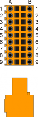 | 1B | 41 | 3 | Down |
| 34 | 1 | Up | 2A | 2B | 42 | 4 | ON | |
| 35 | 1 | Down | 3A | 3B | 43 | 4 | Up | |
| 36 | 2 | ON | 4A | 4B | 44 | 4 | Down | |
| 37 | 2 | Up | 5A | 5B | 45 | 5 | ON | |
| 38 | 2 | Down | 6A | 6B | 46 | 5 | Up | |
| 39 | 3 | ON | 7A | 7B | 47 | 5 | Down | |
| 40 | 3 | Up | 8A | 8B | 48 | 6 | ON | |
| V+ | +24 Volt | 9A | 9B | V+ | +24 Volt |
3.3.5 SLOT 4 (H1-P16 : Out +24 Volt, 500 mA)
| n.Out | Head | Description | Pin | Connector SLOT 4 | Pin | n.Out | Head | Description |
|---|---|---|---|---|---|---|---|---|
| 49 | 6 | Up | 1A | | 1B | 57 | 9 | ON |
| 50 | 6 | Down | 2A | 2B | 58 | 9 | Up | |
| 51 | 7 | ON | 3A | 3B | 59 | 9 | Down | |
| 52 | 7 | Up | 4A | 4B | 60 | 10 | ON | |
| 53 | 7 | Down | 5A | 5B | 61 | 10 | Up | |
| 54 | 8 | ON | 6A | 6B | 62 | 10 | Down | |
| 55 | 8 | Up | 7A | 7B | 63 | 11 | ON | |
| 56 | 8 | Down | 8A | 8B | 64 | 11 | Up | |
| V+ | +24 Volt | 9A | 9B | V+ | +24 Volt |
3.3.6 SLOT 5 (H1-P16 : Out +24 Volt, 500 mA)
| n.Out | Head | Description | Pin | Connector SLOT 5 | Pin | n.Out | Head | Description |
|---|---|---|---|---|---|---|---|---|
| 65 | 11 | Down | 1A | | 1B | 73 | 14 | Up |
| 66 | 12 | ON | 2A | 2B | 74 | 14 | Down | |
| 67 | 12 | Up | 3A | 3B | 75 | 15 | ON | |
| 68 | 12 | Down | 4A | 4B | 76 | 15 | Up | |
| 69 | 13 | ON | 5A | 5B | 77 | 15 | Down | |
| 70 | 13 | Up | 6A | 6B | 78 | 16 | ON | |
| 71 | 13 | Down | 7A | 7B | 79 | 16 | Up | |
| 72 | 14 | ON | 8A | 8B | 80 | 16 | Down | |
| V+ | +24 Volt | 9A | 9B | V+ | +24 Volt |
3.3.7 SLOT 6 (H1-P16 : Out +24 Volt, 500 mA)
| n.Out | Head | Description | Pin | Connector SLOT 6 | Pin | n.Out | Head | Description |
|---|---|---|---|---|---|---|---|---|
| 81 | 17 | ON | 1A | | 1B | 89 | 19 | Down |
| 82 | 17 | Up | 2A | 2B | 90 | 20 | ON | |
| 83 | 17 | Down | 3A | 3B | 91 | 20 | Up | |
| 84 | 18 | ON | 4A | 4B | 92 | 20 | Down | |
| 85 | 18 | Up | 5A | 5B | 93 | 21 | ON | |
| 86 | 18 | Down | 6A | 6B | 94 | 21 | Up | |
| 87 | 19 | ON | 7A | 7B | 95 | 21 | Down | |
| 88 | 19 | Up | 8A | 8B | 96 | 22 | ON | |
| V+ | +24 Volt | 9A | 9B | V+ | +24 Volt |
3.3.8 SLOT 7 (H1-P16 : Out +24 Volt, 500 mA)
| n.Out | Head | Description | Pin | Connector SLOT 7 | Pin | n.Out | Description |
|---|---|---|---|---|---|---|---|
| 97 | 22 | Up | 1A | | 1B | 105 | n.u. |
| 98 | 22 | Down | 2A | 2B | 106 | n.u. | |
| 99 | n.u. | 3A | 3B | 107 | n.u. | ||
| 100 | n.u. | 4A | 4B | 108 | n.u. | ||
| 101 | n.u. | 5A | 5B | 109 | n.u. | ||
| 102 | n.u. | 6A | 6B | 110 | n.u. | ||
| 103 | n.u. | 7A | 7B | 111 | n.u. | ||
| 104 | n.u. | 8A | 8B | 112 | n.u. | ||
| V+ | +24 Volt | 9A | 9B | V+ | +24 Volt |
3.4 RMC-3M B01 MV
| |
| General view RMC-3M |
| |
| bus composition RMC-3M |
3.4.1 RMC-3M B01 MV- Power supply
| CN 1 | Clamp | Symbol | Description | |
|---|---|---|---|---|
| | | 1 | | 0V |
| 2 | GROUND | Ground | ||
| 3 | | +24 V | ||
3.4.2 Connections
3.4.2.1 RMC-3M B01 MV: CN2 - CN3 - CAN PORT
| | 1 | 0 Volt - CanOpen common port |
| 2 | CAN L | |
| 3 | CAN H |
3.4.2.1.1 Wiring example
3.4.2.2 Switch 1
| SW1 | Num. DIP | Set | Function |
|---|---|---|---|
 | 1 | OFF | DIP 1-2: Transmission speed (500 Kbit/s ) |
| 2 | ON | ||
| 3 | OFF | DIP 3-8: Module address (address 2) |
|
| 4 | ON | ||
| 5 | OFF | ||
| 6 | OFF | ||
| 7 | OFF | ||
| 8 | OFF |
3.4.2.3 Switch 3
Check connection CAN to determine the activation of the terminating resistor
| SW3 | Num. Dip | Name Dip | Setting DIP | Function |
|---|---|---|---|---|
| | 1 | JP1 | ON | Termination CAN PORT |
| 2 | JP2 | ON | ||
| 3 | ||||
| 4 |
3.4.3 RMC-3M B01 MV: Digital Inputs
3.4.4 SLOT 3 (H1- I16)
| n.In | Sensor | Description | Pin | Connector SLOT 3 | Pin | Description | Sensor | n.In |
|---|---|---|---|---|---|---|---|---|
| +24V | Out 24 Volt | 1A | | 1B | 0Vdc | 0V | ||
| 33 | 1 | 2A | 2B | 9 | 41 | |||
| 34 | 2 | 3A | 3B | 10 | 42 | |||
| 35 | 3 | 4A | 4B | 11 | 43 | |||
| 36 | 4 | 5A | 5B | 12 | 44 | |||
| 37 | 5 | 6A | 6B | 13 | 45 | |||
| 38 | 6 | 7A | 7B | 14 | 46 | |||
| 39 | 7 | 8A | 8B | 15 | 47 | |||
| 40 | 8 | 9A | 9B | 16 | 48 |
3.4.5 SLOT 4 (H1- I16)
| n.In | Sensor | Description | Pin | Connector SLOT 4 | Pin | Description | Sensor | n.In |
|---|---|---|---|---|---|---|---|---|
| +24V | Out 24 Volt | 1A | | 1B | 0Vdc | 0V | ||
| 49 | 17 | 2A | 2B | 25 | 57 | |||
| 50 | 18 | 3A | 3B | 26 | 58 | |||
| 51 | 19 | 4A | 4B | 27 | 59 | |||
| 52 | 20 | 5A | 5B | 28 | 60 | |||
| 53 | 21 | 6A | 6B | 29 | 61 | |||
| 54 | 22 | 7A | 7B | 30 | 62 | |||
| 55 | 23 | 8A | 8B | 31 | 63 | |||
| 56 | 24 | 9A | 9B | 32 | 64 |
3.4.6 SLOT 5 (H1- I16)
| n.In | Sensor | Description | Pin | Connector SLOT 5 | Pin | Description | Sensor | n.In |
|---|---|---|---|---|---|---|---|---|
| +24V | Out 24 Volt | 1A | | 1B | 0Vdc | 0V | ||
| 65 | 33 | 2A | 2B | 41 | 73 | |||
| 66 | 34 | 3A | 3B | 42 | 74 | |||
| 67 | 35 | 4A | 4B | 43 | 75 | |||
| 68 | 36 | 5A | 5B | 44 | 76 | |||
| 69 | 37 | 6A | 6B | 45 | 77 | |||
| 70 | 38 | 7A | 7B | 46 | 78 | |||
| 71 | 39 | 8A | 8B | 47 | 79 | |||
| 72 | 40 | 9A | 9B | 48 | 80 |
3.4.7 SLOT 6 (H1- I16)
| n.In | Sensor | Description | Pin | Connector SLOT 6 | Pin | Description | Sensor | n.In |
|---|---|---|---|---|---|---|---|---|
| +24V | Out 24 Volt | 1A | | 1B | 0Vdc | 0V | ||
| 81 | 49 | 2A | 2B | 57 | 89 | |||
| 82 | 50 | 3A | 3B | 58 | 90 | |||
| 83 | 51 | 4A | 4B | 59 | 91 | |||
| 84 | 52 | 5A | 5B | 60 | 92 | |||
| 85 | 53 | 6A | 6B | 61 | 93 | |||
| 86 | 54 | 7A | 7B | 62 | 94 | |||
| 87 | 55 | 8A | 8B | 63 | 95 | |||
| 88 | 56 | 9A | 9B | 64 | 96 |
3.4.8 RMC-3M B01 MV: Analogic Inputs
3.4.9 SLOT 7 (H1-A41)
| Connector SLOT 7 | Pin | Name | Description | |
|---|---|---|---|---|
| | 1A | n.c | ||
| 2A | ||||
| 3A | ||||
| 4A | ||||
| 5A | ||||
| 6A | ||||
| 7A | AI4 | Slab Height | ||
| 8A | n.c | |||
| 9A | GAI | Common analogic inputs | ||
| 1B | n.c | |||
| 2B | ||||
| 4B | ||||
| 5B | ||||
| 6B | ||||
| 7B | AI5 | n.c | ||
| 8B | AI6 | n.c | ||
| 9B | GAI | Common analogic inputs | ||
3.5 RMC-3M B01 MZ
Optional module in case the reading of abrasive consumption is required
| |
| General view RMC-3M |
|
| Bus composition del RMC-3M |
3.5.1 RMC-3M C01 D5- Power supply
| CN 1 | Clamp | Symbol | Description | |
|---|---|---|---|---|
| | | 1 | | 0V |
| 2 | GROUND | Ground | ||
| 3 | | +24 V | ||
3.5.2 Connections
3.5.2.1 RMC-3M B01 MZ: CN2 - CN3 - PORTA CAN
| | 1 | 0 Volt - Common port CanOpen |
| 2 | CAN L | |
| 3 | CAN H |
3.5.2.1.1 Wiring example
3.5.2.2 Switch 1
| SW1 | Num. DIP | Set | Function |
|---|---|---|---|
 | 1 | OFF | DIP 1-2: Transimission speed (500 Kbit/s ) |
| 2 | ON | ||
| 3 | ON | DIP 3-8: Module address (address 3) | |
| 4 | ON | ||
| 5 | OFF | ||
| 6 | OFF | ||
| 7 | OFF | ||
| 8 | OFF |
3.5.2.3 Switch 3
Check wiring CAN to determine the activation of the terminating resistor
| SW3 | Num. Dip | Name Dip | Setting DIP | Function |
|---|---|---|---|---|
| | 1 | JP1 | ON | Termination CAN PORT |
| 2 | JP2 | ON | ||
| 3 | ||||
| 4 |
3.5.3 RMC-3M B01 MZ: Analogic inputs
3.5.4 SLOT 3 (H1-A41)
| Connector SLOT 3 | Pin | Name | Description |
|---|---|---|---|
| | 1A | +24V | +24V dc |
| 2A | - | ||
| 3A | |||
| 4A | |||
| 5A | |||
| 6A | |||
| 7A | AI7 | Abrasive 1 | |
| 8A | VREF | Reference voltage | |
| 9A | - | ||
| 1B | |||
| 2B | |||
| 4B | |||
| 5B | |||
| 6B | |||
| 7B | AI8 | Abrasive 2 | |
| 8B | AI9 | Abrasive 3 | |
| 9B | GAI | Common analogic inputs | |
3.5.5 SLOT 4 (H1-A41)
| Connector SLOT 4 | Pin | Name | Description |
|---|---|---|---|
| | 1A | +24V | Uscita +24V dc |
| 2A | - | ||
| 3A | |||
| 4A | |||
| 5A | |||
| 6A | |||
| 7A | AI10 | Abrasive 4 | |
| 8A | VREF | Reference voltage | |
| 9A | - | ||
| 1B | |||
| 2B | |||
| 4B | |||
| 5B | |||
| 6B | |||
| 7B | AI11 | Abrasive 5 | |
| 8B | AI12 | Abrasive 6 | |
| 9B | GAI | Common analog inputs | |
3.5.6 SLOT 5 (H1-A41)
| Connector SLOT 5 | Pin | Name | Description |
|---|---|---|---|
| | 1A | +24V | +24Vdc |
| 2A | - | ||
| 3A | |||
| 4A | |||
| 5A | |||
| 6A | |||
| 7A | AI13 | Abrasive 7 | |
| 8A | VREF | Reference voltage | |
| 9A | - | ||
| 1B | |||
| 2B | |||
| 4B | |||
| 5B | |||
| 6B | |||
| 7B | AI14 | Abrasive 8 | |
| 8B | AI15 | Abrasive 9 | |
| 9B | GAI | Common analogic inputs | |
3.5.7 SLOT 6 (H1-A41)
| Connector SLOT 6 | Pin | Name | Description |
|---|---|---|---|
| | 1A | +24V | +24Vdc |
| 2A | - | ||
| 3A | |||
| 4A | |||
| 5A | |||
| 6A | |||
| 7A | AI16 | Abrasive 10 | |
| 8A | VREF | Reference voltage | |
| 9A | - | ||
| 1B | |||
| 2B | |||
| 4B | |||
| 5B | |||
| 6B | |||
| 7B | AI17 | Abrasive 11 | |
| 8B | AI18 | Abrasive 12 | |
| 9B | GAI | Common analogic inputs | |
4. Support
For supplying you fast service, at the lowest cost, we need your support.
 | 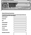 |
| Follow all instructions provided in the MIMAT manual | If the problem remains, fill out the “Request Form for assistance” on the page Contacts at www.qem.it site. Our technicians will get elements essential for the understanding of your problem. |
Repair
To provide you with an efficient service, please read and adhere to the instructions given here
Shipping
It is recommended to pack the instrument with materials that are able to cushion any falls.
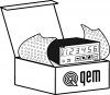 |  |  |
| Use the original package: it must protect the instrument during transport. | Attach: 1. A description of the anomaly; 2. A part of the electric scheme where the equipment is inserted 3. The planning of the equipment (set up, quotas of job, parameters…). 4. Request a quote for repair; if not required, the cost will be calculated in the final balance. | A full description of the problem, will help identify and resolve your problems fast. A careful packaging will avoid further inconveniences. |