MCE_P1P20F - 022 : Connections
1. Informations
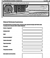
1.1 Release
| |
|||
| Document: | mce_p1p20f-022 | ||
|---|---|---|---|
| Description: | Electrical Connections Manual p1p20f-022 | ||
| Editor: | Omar Sbalchiero | ||
| Approver | Gabriele Bazzi | ||
| Link: | https://www.qem.eu/doku/doku.php/en/strumenti/qmoveplus/j1p20/p1p20f-022/mce_p1p20f-022 | ||
| Language: | English | ||
| Release document | Description | Note | Date |
| 01 | New manual | 18/09/2020 | |
1.1.1 Specifications/Copyright
The copyright to this manual are reserved. For no reason, this document may be copied or reproduced in any form without the QEM permission.
QEM has no assurances or warranties regarding to content. Qem disclaims any responsibility relating to warranties of fitness for any particular purpose. The informations in this document are subject to change without notice. QEM not assumes responsibility for any error that may appear in this document
Trademarks :
-
QEM® is a registered trademark.
-
Microsoft® and MS-DOS® ar registered trademarks of Windows® and it is a trademark of the Microsoft Corporation.
2. Description
The P1P20F - 022 software, controls the automation of polishing machine max 20 heads.
N.B.
-
If you want to separately control the activation of the head motors with the lower and lift of the heads, you need to use the remote I/O module (RMC3M).
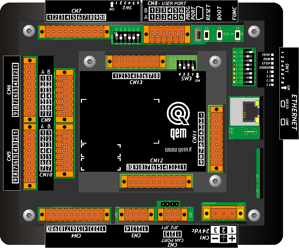
3. Hardware and connections
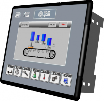
3.1 Operator panel
 |
|
 |
|
 | MIMJ1P20Fx_BASE:Installation and Maintenance Manual |
3.2 Power supply
The instrument will need to be powered to 24Vdc. Install an external fuse in series to the positive conductor +24Volt.
| PIN | ID | DESCRIPTION | |
|---|---|---|---|
 | 1 | +24V | Positive power supply +24Vdc |
| 2 | PE | Ground-PE | |
| 3 | 0V | Common power supply 0Vdc |
3.3 Connectivity
Nr. 1 PROG PORT → Serial with logical TTL standards for programming
Nr. 1 ETHERNET PORT
Nr. 1 CAN PORT for connection with external I/O module
3.3.1 PROG PORT (USB mini-B)

3.3.2 ETHERNET port
| ETHERNET PORT | Description |
|---|---|
 | Connector RJ45. LED: * LINK: green led = cable connected (led on signals the cable is connected to both ends) * DATA: yellow led = data transmission (flashing led signals data transmission) |
3.3.3 CANbus PORT
3.3.3.1 CN2
| Terminal | Symbol | Description | |
|---|---|---|---|
 | 1 | CAN H | CAN H terminal |
| 2 | CAN L | CAN L terminal | |
| 3 | 0V | CAN common |
3.3.3.1.1 Terminating Resistance Setting
| Name jumper | Setting | Function | |
|---|---|---|---|
JP1 JP2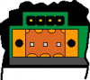 | JP1 | INSERTED | Termination CAN activate |
| JP2 |
3.3.3.1.2 Baud-rate CANbus selector
| SW1 | Dip | DIP setting | Function |
|---|---|---|---|
 | 1 | - | - |
| 2 | - | - | |
| 3 | - | - | |
| 4 | - | - | |
| 5 | ON | Speed selection of CANbus transmission |
|
| 7 | ON | ||
| Baud-rate 1MB/S |
|||
| 6 | - | - | |
| 8 | - | - | |
3.3.3.1.3 Connection example

3.4 Digital inputs
| S = State | A = Action | ID |
|---|---|---|
| NO = Normally Open | I = Impulsive | ID = Software |
| NC = Normally close | C = Continuous |
3.4.1 CN6
| PIN | ID | DESCRIPTION | S | A | |||
|---|---|---|---|---|---|---|---|
 | 1 | 0V | Digital inputs common - Connected internally to 0Volt (PIN 3 - CN1) | ||||
| 2 | I1 | Emergency | - | NC | C | ||
| 3 | I2 | Descent Heads/Start Motors | OFF = Descent Heads ON = Start Motors | NO | C | ||
| 4 | I3 | Motors start | Function enabled with MP-05 = 1 o 2 parameter Start rolling activation of motors | NO | I | ||
| 5 | I4 | Enabled auxiliaries | Machine ready to work | NO | C | ||
| 6 | I5 | NE | Automatically, stop the bridge and conveyor/Reset the message “incorrect start rotating motors” | NC | C | ||
| 7 | I6 | Thermals | Thermals line | ||||
| 8 | I7 | Carter | Protections line | ||||
| 9 | I8 | Pressure switch | Without air | ||||
3.4.1.1 Connection example

3.4.2 CN5
| PIN | ID | DESCRIPTION | S | A | ||||
|---|---|---|---|---|---|---|---|---|
| | 1 | 0V | Digital inputs common - Connected internally to 0Volt (PIN 3 - CN1) | |||||
| 2 | I9 | Piece acquisition | Piece acquisition limit switch | NO | C | |||
| 3 | I10 | n.u. | - | - | - | |||
| 4 | I11 | n.u. | - | - | - | |||
| 5 | I12 | Fault inverter | Inverter alarm | NC | C | |||
| 6 | I13 | Forward bridge | Limit switch | With fast speed | (MP-04 = 1) | |||
| 7 | I14 | Backward bridge | ||||||
| 8 | I15 | Forward slowing bridge | With slow speed | NO | C | |||
| 9 | I16 | Backward slowing bridge | ||||||
3.4.2.1 Connection example

3.5 Digital outputs
| S = State | ID |
|---|---|
| OFF | ID = Software |
| ON |
3.5.1 CN7
| PIN | ID | DESCRIPTION | S | |||
|---|---|---|---|---|---|---|
 | 1 | V+ | Input power outputs O1÷O8 (12÷28Vdc) | |||
| 2 | O1 | Head | 1 | Head descent or motor start control | OFF | |
| 3 | O2 | 2 | ||||
| 4 | O3 | 3 | ||||
| 5 | O4 | 4 | ||||
| 6 | O5 | 5 | ||||
| 7 | O6 | 6 | ||||
| 8 | O7 | 7 | ||||
| 9 | O8 | 8 | ||||
| 10 | V- | Input power outputs (0Vdc) | ||||
3.5.1.1 Connection example

3.5.2 CN4
| PIN | ID | DESCRIPTION | S | |||
|---|---|---|---|---|---|---|
| | 1 | V+ | Input power outputs O9÷O16 (12÷28Vdc) | |||
| 2 | O9 | Head | 9 | Head descent or motor start control | OFF | |
| 3 | O10 | 10 | ||||
| 4 | O11 | 11 | ||||
| 5 | O12 | 12 | ||||
| 6 | O13 | 13 | ||||
| 7 | O14 | 14 | ||||
| 8 | O15 | 15 | ||||
| 9 | O16 | 16 | ||||
| 10 | V- | Input power outputs (0Vdc) | ||||
3.5.2.1 Connection example

3.5.3 CN12
| PIN | ID | DESCRIPTION | S | |||
|---|---|---|---|---|---|---|
| | 1 | V+ | Input power outputs O17÷O24 (12÷28Vdc) | |||
| 2 | O17 | Descent Heads/Start Motors | Descent heads and Start motors command OFF = Descent Heads ON = Start Motors | - | OFF | |
| 3 | O18 | End of start motors | Signals the completion of the cascade motor start cycle. | - | OFF | |
| 4 | O19 | Mix Out | Functions of the mix cycle, with activation and deactivation times settable in set-up. | - | - | |
| 5 | O20 | Piece alarm | Activated when the number of pieces in simultaneous operations is equal to or greater than 30 | - | - | |
| 6 | O21 | Conveyor direction | OFF = forward ON = backward | - | - | |
| 7 | O22 | Bridge direction | OFF = forward ON = backward | - | - | |
| 8 | O23 | Brush | The output is activated when there is at least one piece in the machine | - | - | |
| 9 | O24 | Water valve | - | - | - | |
| 10 | V- | Input power outputs (0Vdc) | ||||
3.5.3.1 Connection example

3.6 Bi-directional counter inputs
3.6.1 CN9
3.6.1.1 For "Push Pull" encoder type
| PIN | ID | DESCRIPTION | ||||
|---|---|---|---|---|---|---|
 | 1A | +24V | Encoder power supply | Conveyor | ||
| 2A | PHA1 | Phase A | ||||
| 3A | PHB1 | Phase B | ||||
| 4A | Z1 | n.u. | ||||
| 5A | 0V | ∩ | Counter inputs common - Connected internally to 0Volt (PIN 3 - CN1) Connect to PIN 5B |
|||
| 6A | Connect to PIN 6B | |||||
| 7A | Connect to PIN 7B | |||||
3.6.1.1.1 Connection example

3.6.1.2 For "Line Driver" encoder type
| PIN | ID | DESCRIPTION | ||||
|---|---|---|---|---|---|---|
| | 1B | +24V | Encoder power supply | Conveyor | ||
| 2B | PHA1+ | Phase A+ | ||||
| 3B | PHB1+ | Phase B+ | ||||
| 4B | Z1+ | n.u. | ||||
| 5B | PHA1- | Phase A- | ||||
| 6B | PHB1- | Phase B- | ||||
| 7B | Z1- | n.u. | ||||
3.6.1.2.1 Connection example
| Only for Encoder powered by the instrument at +24Vdc, with 5 Volt Line Driver outputs |
|---|
 |
| For encoder powered with +5Vdc, with 5 Volt Line Driver outputs |
|---|
 |
3.6.2 CN10
3.6.2.1 For "Push Pull" encoder type
| PIN | ID | DESCRIPTION | ||||
|---|---|---|---|---|---|---|
| | 1A | +24V | Encoder power supply | Bridge | ||
| 2A | PHA2 | Phase A | ||||
| 3A | PHB2 | Phase B | ||||
| 4A | Z2 | n.u. | ||||
| 5A | 0V | ∩ | Counter inputs common - Connected internally to 0Volt (PIN 3 - CN1) Connect to PIN 5B |
|||
| 6A | Connect to PIN 6B | |||||
| 7A | Connect to al PIN 7B | |||||
3.6.2.1.1 Connection example

3.6.2.2 For "Line Driver" encoder type
| PIN | ID | DESCRIPTION | ||||
|---|---|---|---|---|---|---|
| | 1B | +24V | Encoder power supply | Bridge | ||
| 2B | PHA2+ | Phase A+ | ||||
| 3B | PHB2+ | Phase B+ | ||||
| 4B | Z2+ | n.u. | ||||
| 5B | PHA2- | Phase A- | ||||
| 6B | PHB2- | Phase B- | ||||
| 7B | Z2- | n.u. | ||||
3.6.2.2.1 Connection example
| Only for Encoder powered by the instrument at +24Vdc, with 5 Volt Line Driver outputs |
|---|
 |
| For encoder powered with +5Vdc, with 5 Volt Line Driver outputs |
|---|
 |
3.7 Analog outputs
3.7.1 CN3
| PIN | ID | DESCRIPTION | |||
|---|---|---|---|---|---|
 | 1 | GAO | Common of analog outputs | ||
| 2 | AO1 | Output 0-10V | Inverter command | Conveyor | |
| 3 | AO2 | Bridge | |||
| 4 | GAO | Common of analog outputs | |||
3.7.1.1 Connection example

3.8 External I/O module RMC-3MB01-M9/0/0/0/P16/P16/24Vdc
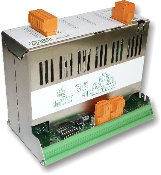 |
|
 |
|
| | RMC-3MB01:Installation and Maintenance Manual |
3.8.1 Power supply
3.8.1.1 CN1
The instrument will need to be powered to 24Vdc. Install an external fuse in series to the positive conductor +24Volt.
| PIN (NUMBER) | ID | DESCRIPTION | |
|---|---|---|---|
 | 1 (1) | 0V | Common power supply 0Vdc |
| 2 (2) | PE | Ground-PE | |
| 3 (3) | +24V | Positive power supply +24Vdc |
3.8.2 Connectivity
3.8.2.1 PROG PORT (USB mini-B)
3.8.2.2 CN2
| PIN (NUMBER) | ID | DESCRIPTION | |
|---|---|---|---|
 | 1 (4) | 0V | CAN common |
| 2 (5) | CAN_L | CAN low signal | |
| 3 (6) | CAN_H | Can high signal |
3.8.2.3 CN3
| PIN (NUMBER) | ID | DESCRIPTION | |
|---|---|---|---|
| | 1 (7) | 0V | CAN common |
| 2 (8) | CAN_L | CAN low signal | |
| 3 (9) | CAN_H | Can high signal |
3.8.2.3.1 Connection example
3.8.2.3.2 Terminating Resistance Setting
| SW3 | Num. Dip | Name Dip | DIP Setting | Function |
|---|---|---|---|---|
 | 1 | JP1 | ON | Termination CAN PORT |
| 2 | JP2 | ON | ||
| 3 | JP1 | NC | ||
| 4 | JP2 | NC |
If you enable the terminating of the CAN port, both the DIP JP1 and JP2 must be enabled.
3.8.2.3.3 Address and speed settings
| SW1 | Nr. DIP | Function | |
|---|---|---|---|
 | CAN transmission speed select | 1 | ON |
| 2 | ON | ||
| Baud-Rate | 1Mb | ||
| CAN transmission address select | 3 | ON | |
| 4 | OFF | ||
| 5 | OFF | ||
| 6 | OFF | ||
| 7 | OFF | ||
| 8 | OFF | ||
| ID | 1 |
3.8.3 Digital outpus
| S = Stato | ID |
|---|---|
| OFF | ID = Software |
| ON |
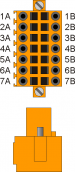
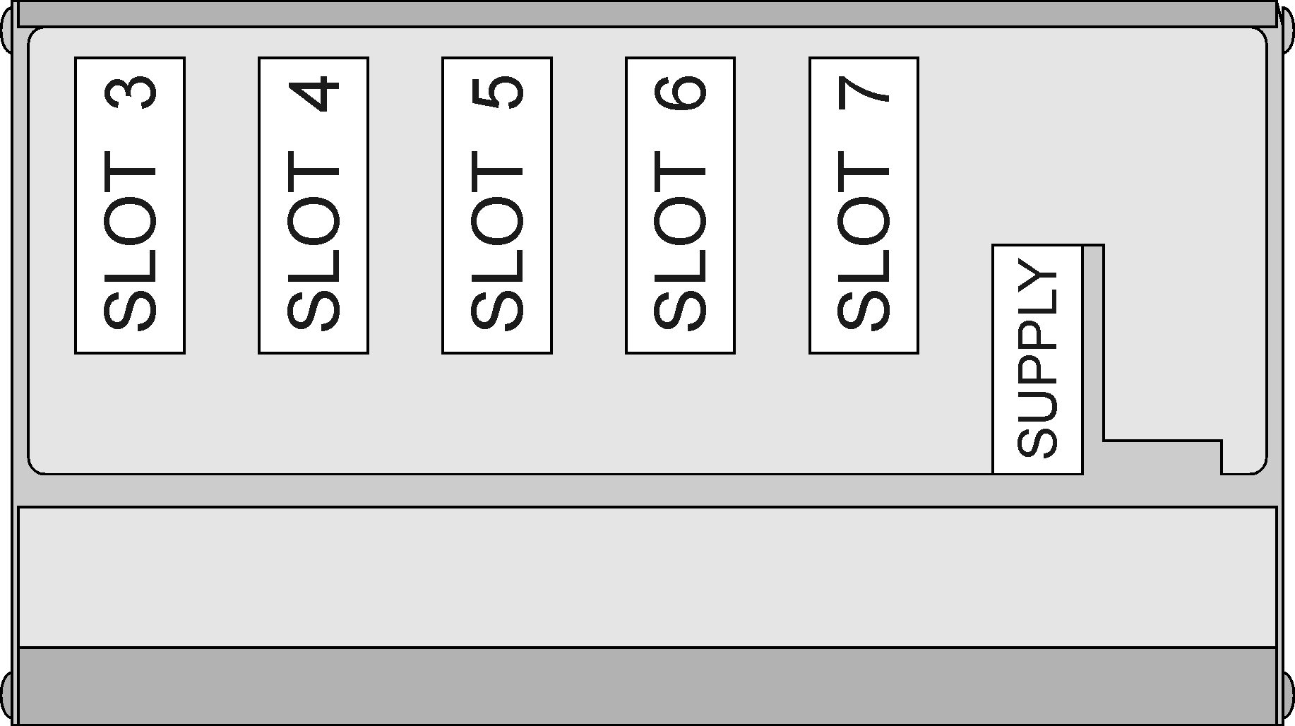
3.8.3.1 SLOT 6
| PIN | ID | DESCRIPTION | S | ||||
|---|---|---|---|---|---|---|---|
 | 1A | O25 | Start Head motor | 1 | OFF | ||
| 2A | O26 | 2 | |||||
| 3A | O27 | 3 | |||||
| 4A | O28 | 4 | |||||
| 5A | O29 | 5 | |||||
| 6A | O30 | 6 | |||||
| 7A | O31 | 7 | |||||
| 8A | O32 | 8 | |||||
| 9A | V1+ | Input power outputs O25÷O32 (12÷28V dc) | - | ||||
| 1B | O33 | Start Head motor | 9 | OFF | |||
| 2B | O34 | 10 | |||||
| 3B | O35 | 11 | |||||
| 4B | O36 | 12 | |||||
| 5B | O37 | 13 | |||||
| 6B | O38 | 14 | |||||
| 7B | O39 | 15 | |||||
| 8B | O40 | 16 | |||||
| 9B | V2+ | Input power outputs O33÷O40 (12÷28V dc) | - | ||||
3.8.3.1.1 Connection example

3.8.3.2 SLOT 7
| PIN | ID | DESCRIPTION | S | ||||
|---|---|---|---|---|---|---|---|
| | 1A | O41 | Start Head Motor | 17 | OFF | ||
| 2A | O42 | 18 | |||||
| 3A | O43 | 19 | |||||
| 4A | O44 | 20 | |||||
| 5A | O45 | Descent Head | 17 | ||||
| 6A | O46 | 18 | |||||
| 7A | O47 | 19 | |||||
| 8A | O48 | 20 | |||||
| 9A | V1+ | Input power outputs O41÷O48 (12÷28V dc) | - | ||||
| 1B | O49 | n.u. | - | - | |||
| 2B | O50 | - | - | ||||
| 3B | O51 | - | - | ||||
| 4B | O52 | - | - | ||||
| 5B | O53 | - | - | ||||
| 6B | O54 | - | - | ||||
| 7B | O55 | - | - | ||||
| 8B | O56 | - | - | ||||
| 9B | V2+ | Input power outputs O49÷O56 (12÷28V dc) | - | ||||
3.8.3.2.1 Connection example

4. Assistance
For supplying you fast service, at the lowest cost, we need your support.
 |  |
| Follow all instructions provided in the MIMAT manual | If the problem remains, fill out the “Request Form for assistance” on the page Contacts at www.qem.it site. Our technicians will get elements essential for the understanding of your problem. |
Repair
To provide you with an efficient service, please read and adhere to the instructions given here
Shipping
It is recommended to pack the instrument with materials that are able to cushion any falls.
 |  |  |
| Use the original package: it must protect the instrument during transport. | Attach: 1. A description of the anomaly; 2. A part of the electric scheme where the equipment is inserted 3. The planning of the equipment (set up, quotas of job, parameters…). 4. Request a quote for repair; if not required, the cost will be calculated in the final balance. | A full description of the problem, will help identify and resolve your problems fast. A careful packaging will avoid further inconveniences. |